
Intervertebral implant with tiltable joint parts

a technology of intervertebral implants and joint parts, which is applied in the field of intervertebral implants, can solve the problems of abrasion and resistance, wear on the surface, and generating disadvantageous friction forces, and achieve the effect of facilitating the insertion into the intervertebral spa

Active Publication Date: 2013-03-05
SYNTHES USA
View PDF10 Cites 8 Cited by
  • Summary
  • Abstract
  • Description
  • Claims
  • Application Information

AI Technical Summary

Benefits of technology

The patent text describes a new process for implanting intervertebral implants that reduces friction between joint sections, allowing for relative movement between the vertebral bodies. This results in improved mobility of the spinal column. Additionally, the text discusses the use of a device to block the joints on the implant, which can help alleviate post-operative pain or provide temporary stiffening of the affected movement segment of the spinal column. The blocking can be done in a minimally invasive laparoscopic operation.

Problems solved by technology

The disadvantages of this known intervertebral disk endoprosthesis is that
c) disadvantageous friction forces are generated by two articulating surfaces sliding on each other.
This also leads to wear on the surfaces, including also abrasion and resistance in movement of the joint elements.
There is also the risk of the “stick slip” effect;
d) a mechanical intervertebral disk prosthesis can scarcely prevent the further degeneration of the affected movement segments.
This operation represents extreme discomfort and strain on the patient; and

Method used


Image

  • Intervertebral implant with tiltable joint parts
  • Intervertebral implant with tiltable joint parts
  • Intervertebral implant with tiltable joint parts

Examples


Embodiment Construction

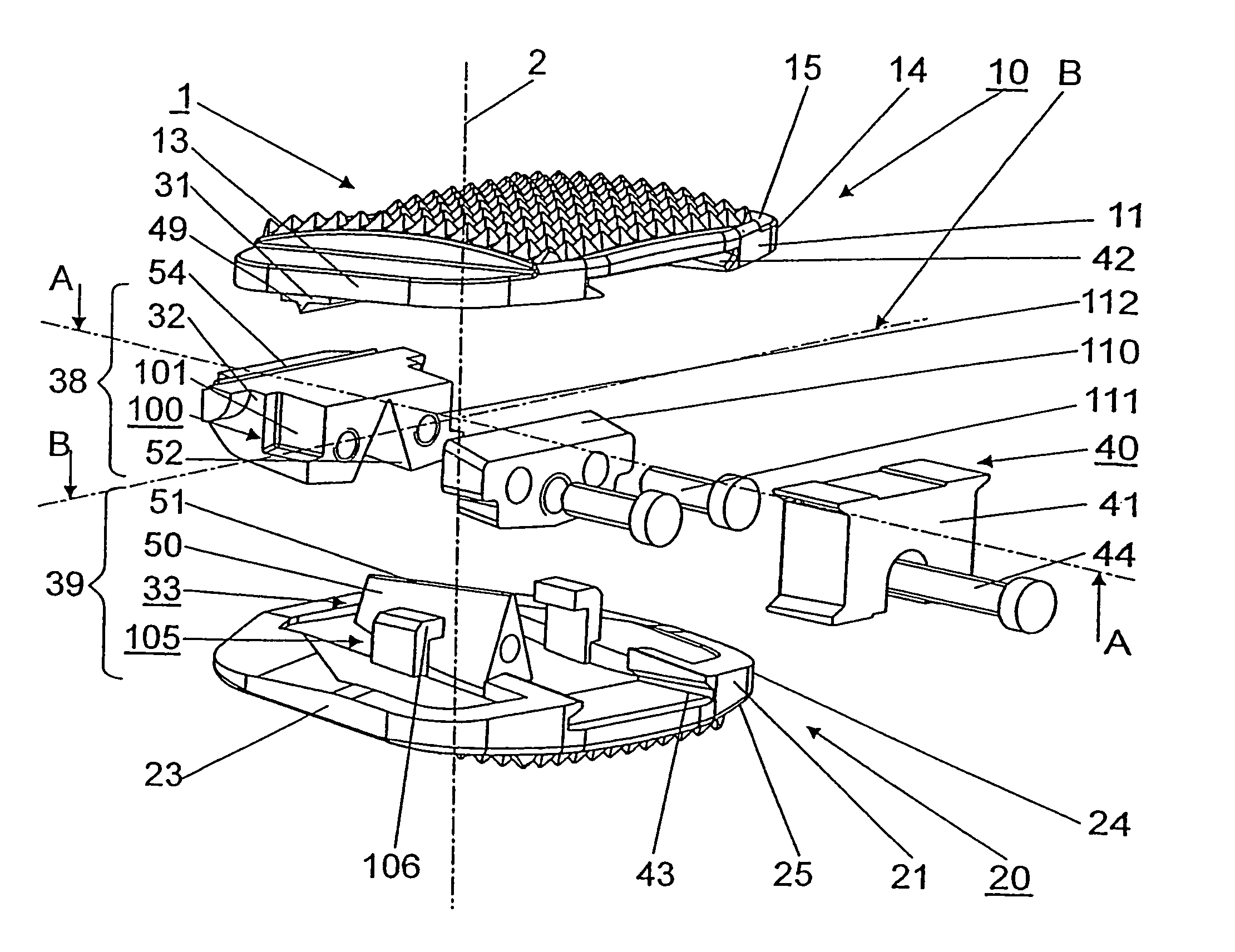
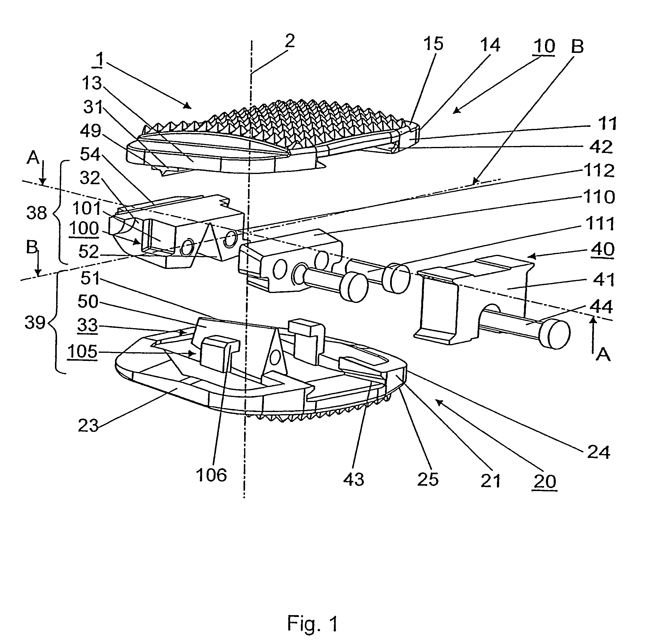
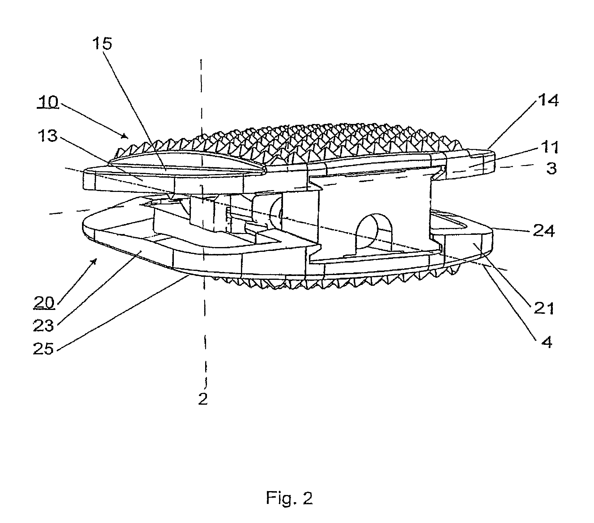
[0030]FIG. 1 and FIG. 2 show an embodiment of the intervertebral implant 1 according to the invention, which comprises an upper section 10 with a top apposition surface 15 arranged perpendicular to the central axis 2 for laying on the base plate of an adjoining vertebral body, a lower section 20 with a lower apposition surface 25 arranged perpendicular to the central axis 2 for laying on the cover plate of the adjoining vertebral body and two joints 38;39. The upper section 10 further including a ventral side area 11, a dorsal side area 12, two lateral side areas 13, 14, and a bottom surface 16. The lower section further including a ventral side area 21, a dorsal side area 22, two lateral side areas 23,24, and a top surface 26. The upper section 10 and the lower section 20 are connected with the joints 38;39 and moveable in relation to each other, whereby the mobility of the upper section 10 relative to the lower section 20 is restricted by a first swivel axle 3 arranged perpendicul...


PUM


Abstract

An intervertebral implant (1) including an upper section (10) provided with a ventral side area (11), a dorsal side area (12), two lateral side areas (13, 14), a top apposition surface (15) and a bottom surface (16), a lower section (20) provided with a ventral side area (21), a dorsal side area (22), two lateral side areas (23,24), a bottom apposition surface (25) and a top surface (26). The two sections (10,20) are moveable in relation to each other by means of two joints (38;39) arranged between the two sections (10;20), wherein each of the joints (38;39) has a swivel axis (3;4) and the two swivel axes (3;4) are arranged perpendicular to each other, and each joint (38;39) comprises a first joint section (31;32;33) with an elevation (49;50) provided with an edge (51;53) for the bearing of a second joint section (31;32;33) in a way that allows titling around the swivel axis (3;4).

Description

BACKGROUND OF THE INVENTION[0001]The invention relates to an intervertebral implant according to the generic term of Patent Claim 1 and to a process for the replacement of a defect, natural intervertebral disk by an intervertebral implant according to.[0002]After removal of a damaged, natural intervertebral disk or a damaged nucleus pulposus of an intervertebral disk, implants or prostheses are inserted into the intervertebral space of two neighbouring vertebral bodies. This suggests the idea of restoring the situation as much as possible to a natural state, i.e. specifically to restore the original height of the intervertebral disk and thus the original distance between the two neighbouring vertebral bodies. Furthermore, the patient should be able to carry out movements of the neighbouring vertebral bodies relative to each other in the natural way, thereby incurring as little obstruction as possible. This essential feature of this system is its ability to retain the freedom of move...

Claims


Application Information

Patent Timeline
Patent Type & Authority Patents(United States)
IPC IPC(8): A61F2/44A61B17/86A61F2/00A61F2/30A61F2/46
CPCA61F2/4425A61B17/86A61F2220/0033A61F2/4455A61F2002/30362A61F2002/30387A61F2002/30393A61F2002/30395A61F2002/30507A61F2002/30515A61F2002/30517A61F2002/30528A61F2002/30604A61F2002/30632A61F2002/30634A61F2002/30774A61F2002/30785A61F2002/30787A61F2002/30794A61F2002/30843A61F2002/443A61F2002/4635A61F2220/0025A61B17/863A61F2002/3079
Inventor AEBI, MAXBURKARD, DOMINIQUEFRIGG, ROBERTLECHMANN, BEATMATHYS, JR., ROBERTPAVLOV, PAUL
Owner SYNTHES USA
Learn More