Electromagnetic support coil and subframe

a support coil and electromagnet technology, applied in the field of electromagnetical tattoo machines, can solve the problems of limiting the adjustment range of the moving parts of the machine, limiting the adjustability or accessibility of the magnetic wire windings of the coil, etc., and achieve the effect of facilitating removal and replacement and improving performan

Inactive Publication Date: 2013-03-12
GODOY ARTHUR ALEXANDER +1
View PDF10 Cites 16 Cited by
  • Summary
  • Abstract
  • Description
  • Claims
  • Application Information

AI Technical Summary

Benefits of technology

[0004]According to an embodiment of the present invention, an object of the V3 Electromagnetic Support Coil Bobbin Assembly (such as shown in more detail in FIG. 4) is to provide an improved electromagnetic tattoo machine with improved performance such as providing for facilitated removal and replacement of retaining washers and O-rings such as between electromagnetic coils and frame members, and to enable a machine operator to further customize, not only the electromagnetic coil's wire windings, but the configuration of the machine as a whole, which may not be possible with traditional “one piece frame” tattoo machines.

Problems solved by technology

The single solid structural frame component commonly used in such existing tattoo machines may typically limit the range of adjustment of the moving parts of the machine, such as the armature bar and needle bar, and the non-moving parts such as the needle tube.
Such single solid structural frame designs may also typically use fixed retaining washers to attach the electromagnetic coil assemblies to the frame, which may limit the adjustability or accessibility of the magnetic wire windings of the coils, such as for custom adjustment or repair, for example.

Method used


Image

  • Electromagnetic support coil and subframe
  • Electromagnetic support coil and subframe
  • Electromagnetic support coil and subframe

Examples


Embodiment Construction

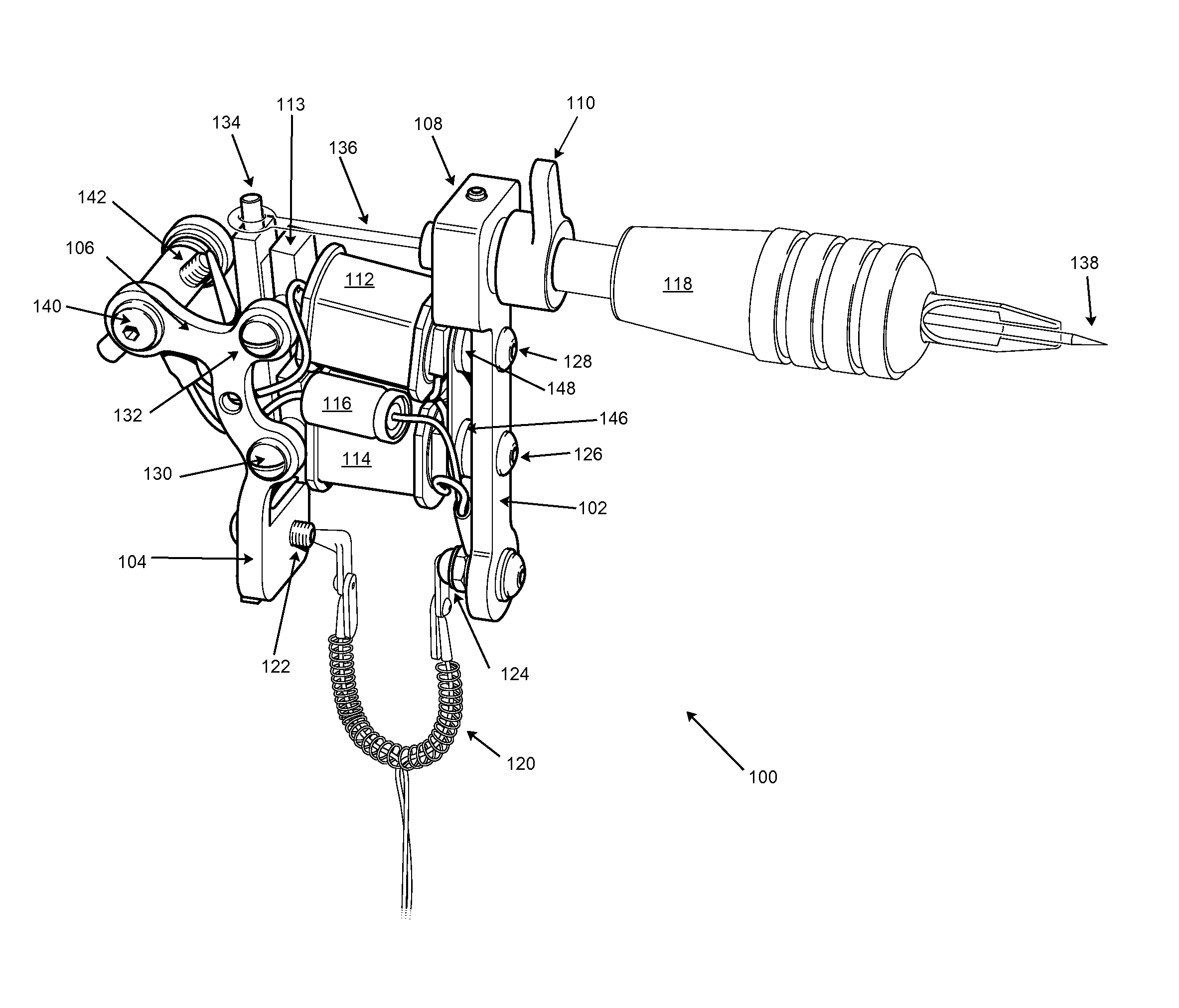
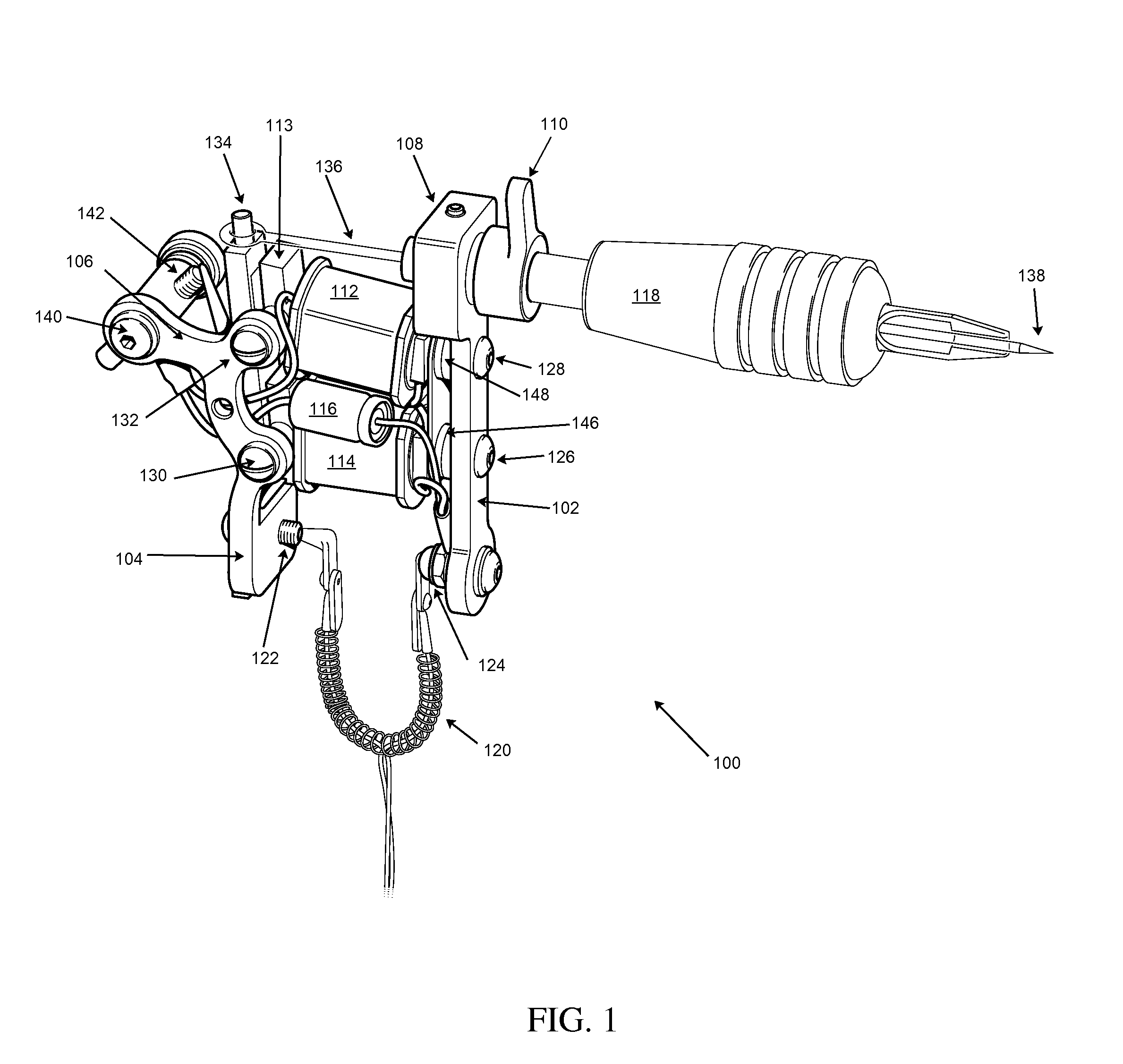
[0024]FIG. 1 illustrates a perspective view of an electromagnetic tattoo machine 100 according to an embodiment of the invention having an electromagnetic support coil assembly 112, 114, and assembled in an exemplary right handed configuration with a two piece support sub-frame comprising a base sub-frame 102 and an upper binding post / saddle sub-frame 104. The base sub-frame 102 may comprise coil mounting spacers 146, 148 adapted for mounting electromagnetic coil assemblies 114 and 112, respectively, such as by means of lower coil mounting screws 126 and 128, for example. The upper binding post / saddle sub-frame 104 may comprise an upper binding post 142 held by an upper binding post bolt 140, and extending from a saddle 106 of the upper binding post / saddle sub-frame 104. The upper binding post / saddle sub-frame 104 may be mounted to the side of an upper mounting flange 113 of the electromagnetic coil assemblies 112 and 114 such as by upper coil mounting screws 132 and 130, respective...


PUM


Abstract

An improved electromagnetic coil tattoo machine offers the operator the opportunity to customize the machine's structural and operating properties. An embodiment of the invention provides a tattoo machine having at least one electromagnetic support coil which may include a coil core which has threaded holes which accommodate fasteners used to structurally secure and support 2 or 3 piece sub-frame members which house the secondary components that a conventional one-piece frame would house—such as the spring / armature bar, the binding posts and the preferred tube vice system. Accordingly in one embodiment, the support coil assemblies themselves act as a primary structural frame member. In a further embodiment, the electromagnetic support coil assembly may also use removable instead of non-removable retaining washers and O-rings to retain magnetic wire windings such as to allow the operator to customize and repair the magnetic wire.

Description

RELATED APPLICATION[0001]The present application claims priority to the following previously filed patent application: U.S. Provisional Patent Application No. 61 / 278,801, filed Dec. 18, 2010 and entitled “Electromagnetic Support Coil and Subframe”, the contents of which are herein incorporated by reference in their entirety.FIELD OF THE INVENTION[0002]The present invention relates generally to the field of tattooing and tattoo machines, and more particularly to electromagnetic tattoo machines having improved electromagnetic support coil assemblies which provide structural support for other tattoo machine components.BACKGROUND TO THE INVENTION[0003]The electromagnetic coil assembly is one of the most important components of any tattoo machine that uses electromagnetism to operate. The electromagnetic coil assembly provides a reciprocating or oscillating motion to a spring mounted magnetic armature bar which in turn drives the reciprocating motion of the tattoo needle for transferring...

Claims


Application Information

Patent Timeline
Patent Type & Authority Patents(United States)
IPC IPC(8): B43K5/00B26F1/00A61B17/34
CPCA61M37/0076
Inventor GODOY, ARTHUR ALEXANDERGODOY, STEPHEN ANDREW
Owner GODOY ARTHUR ALEXANDER
Why Eureka
Try Eureka