Introducer for endovascular grafts and stents

a technology of endovascular grafts and endovascular stents, which is applied in the field of introductions, can solve the problems of proximal end of stent-grafts, prone to incorrect fitting, and difficulty in connection, and achieves better and more reliable seals, good connection, and shorter neck length

Active Publication Date: 2013-03-12
COOK MEDICAL TECH LLC
View PDF17 Cites 14 Cited by
  • Summary
  • Abstract
  • Description
  • Claims
  • Application Information

AI Technical Summary

Benefits of technology

[0009]According to an aspect of the present invention, there is provided an introducer assembly for introducing a stent-graft or other device into a patient, including a catheter provided with a flexible device holding portion onto which a device to be introduced into a patient can be placed, the device holding portion being formed in a curve so as to impart a curvature to a device placed thereon and being able to be trained between substantially straight and curved configurations.
[0027]According to another aspect of the present invention, there is provided a catheter for an introducer assembly for introducing a stent-graft or other device into a patient, the catheter including a flexible device holding portion onto which a device to be introduced into a patient can be placed, the device holding portion being formed in a curve so as to impart a curvature to a device placed thereon and being able to be trained between substantially straight and curved configurations.

Problems solved by technology

Even though such a procedure is possible into the aortic arch, it is mired in difficulties as a result of the tight curvature of the latter.
One such difficulty arises in connection with the proximal end of the stent-graft, which is liable to be incorrectly fitted such that it incompletely seals around the inner wall of the aorta as a result of the curvature imparted to the stent-graft.
This can lead to leakage of blood around the outside of the stent-graft and thus of a less than effective treatment.
Furthermore, as a result of the non-optimal placement of the stent-graft using known procedures, there is a limit to the length of neck of healthy vascular wall which is needed to provide a seal around the proximal end of the stent-graft.
This limits the application of such stent-grafts, in particular for the treatment of aneurysms close to a branch vessel.
In addition, in some instances at least, a part of the proximal end of the stent-graft can remain loosely located in the vessel, leading to premature fatigue failure and thrombus effects.

Method used


Image

  • Introducer for endovascular grafts and stents
  • Introducer for endovascular grafts and stents
  • Introducer for endovascular grafts and stents

Examples


Embodiment Construction

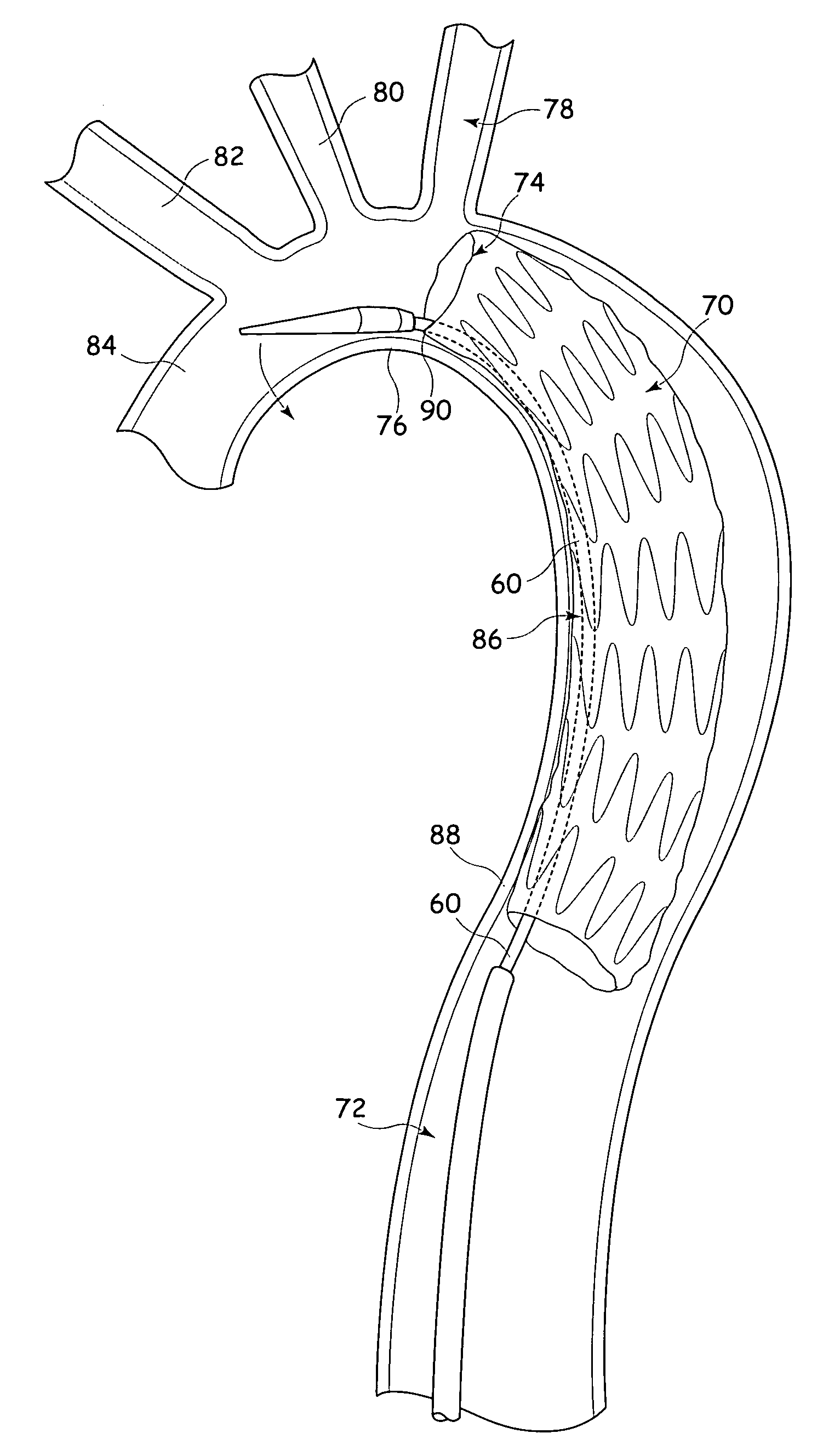
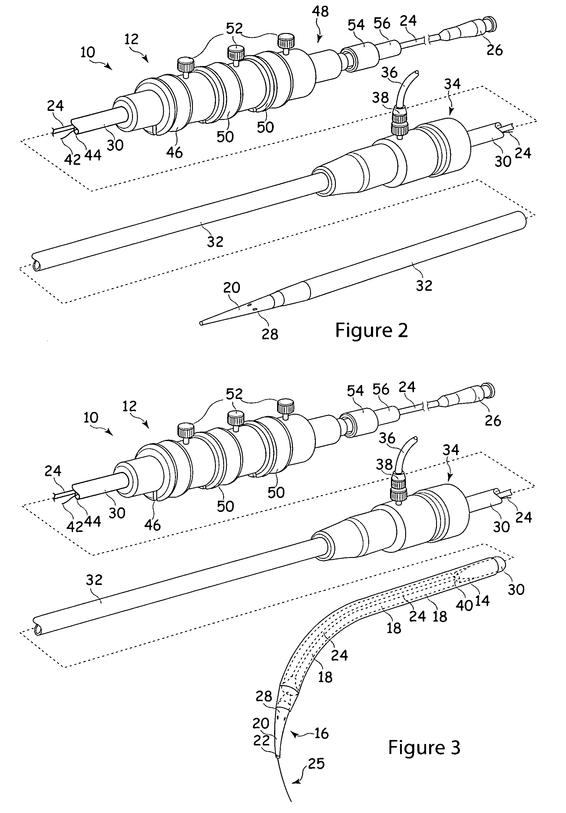
[0035]For the purposes of this disclosure, when used in connection with description of a stent-graft or other implantable device, the term “proximal” refers to a part or position closest to the heart, that is upstream in the direction of blood flow, while the term “distal” refers to a part or position furthest from the heart. On the other hand, when used in connection with an introducer assembly the term “proximal” refers to a position or part closest to the surgeon and typically kept outside the patient, while the term “distal” refers to a position or part furthest from the surgeon and in practice furthest into a patient during a deployment procedure.

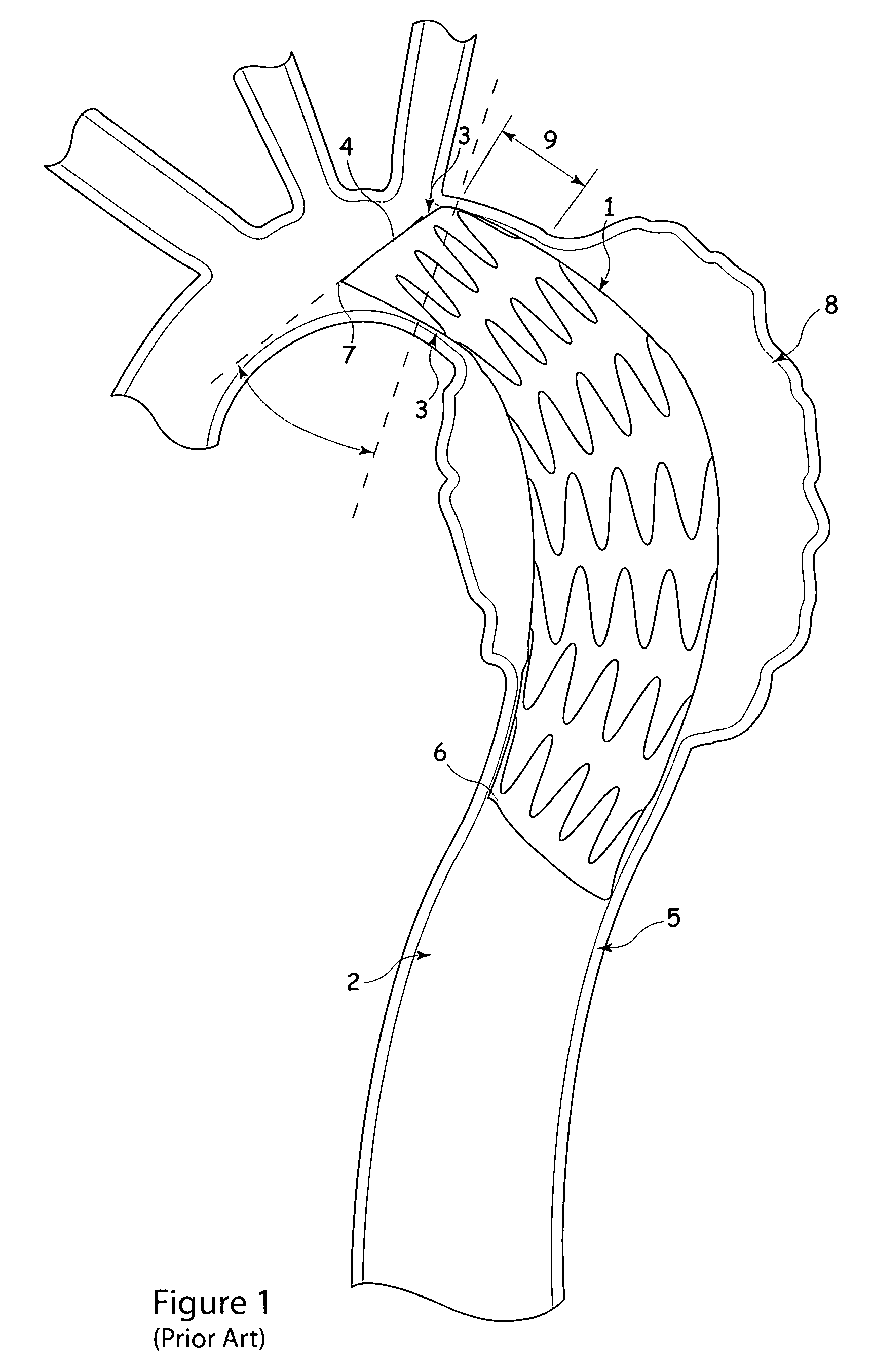
[0036]Referring to FIG. 1, there is shown an example of deployment of a stent-graft 1 within the aorta 2 of a patient for the treatment of, for example, an aneurysm 8. In this particular example, the stent-graft extends part-way into the aortic arch 3 at its proximal end 4, down to the thoracic aorta 5 at its distal end 6. The curvatur...


PUM


Abstract

An introducer assembly for introducing a stent-graft (70) or other device into a vessel of a patient includes a pre-shaped curved cannula (60) made preferably of a shape memory material. The curved cannula can pull the proximal end (74) of the stent-graft (70) against the inner side wall of the vessel thereby to ensure a good leak free connection at this point. The assembly is particularly useful in deploying stent-grafts into the aortic arch.

Description

CROSS-REFERENCE TO RELATED APPLICATIONS[0001]This application claims priority of provisional application Ser. No. 61 / 065,332, filed Feb. 11, 2008.TECHNICAL FIELD[0002]The present invention relates to an introducer for the deployment of implants and prostheses into a body lumen of a patient and in particular for deploying a stent-graft or stent into a patient. The device is particularly suited for the deployment of stent-grafts and stents in the aortic arch.BACKGROUND ART[0003]Prostheses for the repair of vascular defects, including for example vascular aneurysms, are well known in the art. A common prosthesis for treatment of such a medical condition is a stent-graft.[0004]Prostheses of this type are typically deployed endoluminally through a vein or artery adjacent a surface of a patient. For example, aortic prostheses are commonly fed through the femoral artery. A common method of deployment involves the location of a guide wire along the path to be followed by the introducer asse...

Claims


Application Information

Patent Timeline
Patent Type & Authority Patents(United States)
IPC IPC(8): A61F2/06
CPCA61F2/95A61F2/966A61F2/07A61F2250/0029
Inventor JENSEN, KIM MOEGELVANGOHLENSCHLAEGER, BENTRASMUSSEN, ERIK E.
Owner COOK MEDICAL TECH LLC
Why Eureka
Try Eureka