Robot, control device for robot, and control method of robot

a robot and control device technology, applied in the field of robots, can solve the problems of robot action instability, complex control system structure, and difficulty in application of this method, and achieve the effect of preventing the joint from exceeding the movable rang

Active Publication Date: 2013-03-12
PANASONIC CORP
View PDF24 Cites 29 Cited by
  • Summary
  • Abstract
  • Description
  • Claims
  • Application Information

AI Technical Summary

Benefits of technology

[0028]In accordance with the robot, the control device, and the control method for the robot of the present invention, the joint movable-state calculation means and the force conversion means are provided; therefore, even when a person carries out a manipulation that exceeds the movable range of the joint upon operation under an impedance controlling process, the joint movable-state calculation means determines whether or not the joint is located at any position within the movable range and is in a movable state, and by using the converted external force converted by the external force conversion means as input to the impedance calculation means, the operation regulation of the robot arm is made possible, thereby making it possible to prevent the joint from exceeding the movable range.

Problems solved by technology

In the above-mentioned conventional art, however, since this method provides a fixed limiter for regulating the work range of the hand of the robot arm, the application of this method becomes difficult, in a case where the movable range of the hand is changed in a complicated manner due to a relationship among a plurality of joints, such as regulated operation ranges among the respective joints of a robot arm.
Moreover, in the conventional art, with respect to an operation exceeding the limiter, by generating a repulsive force by changing a control parameter, such as a spring constant, the operation is regulated; however, the structure of the control system might become complicated in an attempt to make the control parameter variable.
Furthermore, by changing the control parameter, the control system might become unstable, with the result that the action of the robot might become unstable.

Method used


Image

  • Robot, control device for robot, and control method of robot
  • Robot, control device for robot, and control method of robot
  • Robot, control device for robot, and control method of robot

Examples


first embodiment

(First Embodiment)

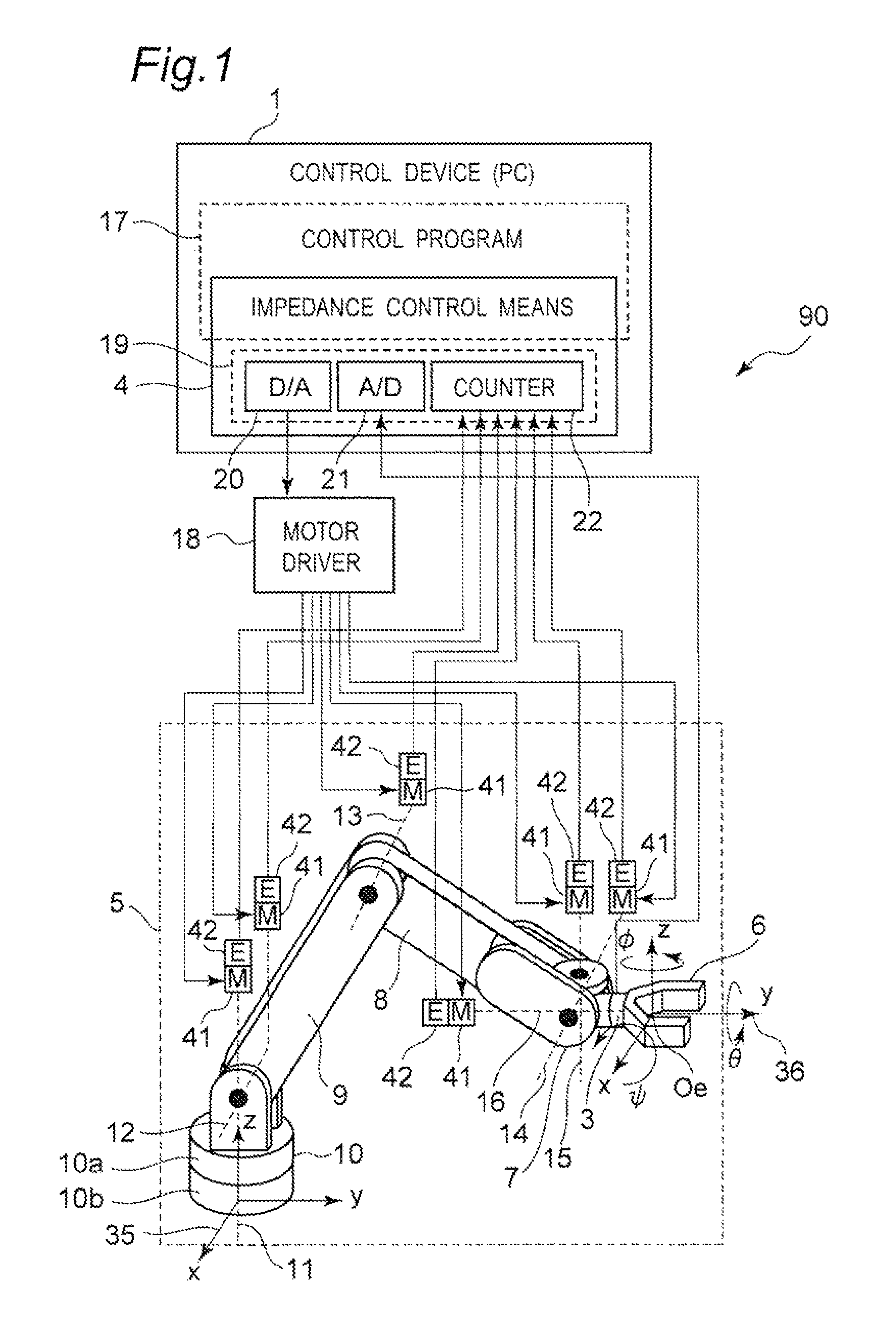
[0086]FIG. 1 is a view illustrating a structure of a robot 90 in accordance with a first embodiment of the present invention. This robot 90 is provided with a multi-joint robot arm 5 and a control device 1 that controls operations of the multi-joint robot arm 5.

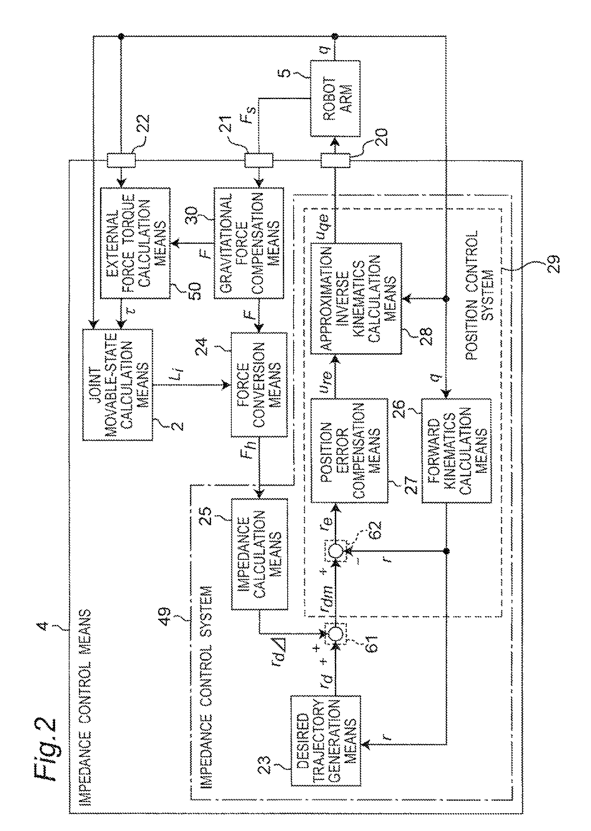
[0087]The control device 1 is configured by a general-use personal computer in its hardware. Moreover, portions except for an input / output IF 19 of an impedance control means (impedance control unit) 4 are achieved as a software control program 17 to be executed by the personal computer.

[0088]The input / output IF 19 is constituted by a D / A board 20, an A / D board 21, and a counter board 22 connected to expansion throttles, such as PCI buses, of the personal computer.

[0089]The control program 17 for use in controlling operations of the multi-joint robot arm 5 of the robot 90 is executed so that the control device 1 is allowed to function. Pieces of joint-angle information, which are outputted from encoders 42 o...

second embodiment

(Second Embodiment)

[0190]A basic structure of a robot in accordance with a second embodiment of the present invention is the same as that of the first embodiment shown in FIGS. 1 and 2; therefore, explanations on the common portions are omitted, and the following description will refer to only different points in detail.

[0191]As shown in FIG. 7, in the second embodiment, force input control means 34 that is independent from normal impedance control means 43 (that is, the impedance calculation means 25, the desired trajectory generation means 23, the forward kinematics calculation means 26, the position error compensation means 27, the approximation inverse kinematics calculation means 28, the first operation unit 61, and the second operation unit 62) is provided with joint movable-state calculation means 2 and force conversion means 24 so that this structure is allowed to communicate with an existing control device (first control device) 1B.

[0192]FIG. 8 illustrates the entire struct...

third embodiment

(Third Embodiment)

[0197]A basic structure of a control device in accordance with a third embodiment of the present invention is the same as that of the first embodiment shown in FIGS. 1 and 2; therefore, explanations on the common portions are omitted, and the following description will refer to only different points in detail.

[0198]FIG. 9 is a block diagram illustrating a structure of impedance control means of a robot 90C in accordance with the third embodiment of the present invention, and FIG. 10 is a view explaining a cooperative transporting job between the robot 90C and a person 100.

[0199]As shown in FIG. 10, in the robot 90C of the third embodiment, an operation handle 40 is secured to a wrist portion 7 with a force sensor 3 interposed therebetween, and the person 100 directly grabs the operation handle 40, and applies a force thereto so as to operate the robot 90C. The force sensor 3 is placed between the operation handle 40 and the robot arm 5 so that the force applied by ...


PUM


Abstract

A robot is provided with a multi-joint robot arm, an external force detection unit that is installed in the arm, and detects an external force, a joint movable-state calculation unit that calculates a movable state of a joint of the arm, an external force conversion unit which, based on the movable state calculated by the joint movable-state calculation unit, converts the external force detected by the external force detection unit to a converted external force, and a control unit that controls the arm based on the converted external force so as to regulate the operation of the arm.

Description

[0001]This is a continuation application of International Application No. PCT / JP2010 / 006271, filed Oct. 22, 2010.BACKGROUND OF THE INVENTION[0002]The present invention relates to a robot that carries out a cooperative job with a person, such as a robot equipped with a robot arm for use in executing a job assist such as a power assist in factories, household, or a nursing care field, a control device and a control method for such a robot.[0003]In recent years, the robot of a person cooperation type that is cooperatively operated with a person in factories and the like so as to carry out a job assist, such as a power assist, has drawn public attentions. Since the robot of such a person cooperation type is allowed to work by a person's manipulation, it is applicable to a practical job without having highly autonomous functions, and since the robot is operated under control of the person, safety is highly ensured, and in the future, such a robot is highly expected to be applied not only...

Claims


Application Information

Patent Timeline
Patent Type & Authority Patents(United States)
IPC IPC(8): G05B15/00B25J9/06B25J13/08
CPCG05B19/423G05B2219/36429G05B2219/39325
Inventor OKAZAKI, YASUNAO
Owner PANASONIC CORP
Why Eureka
Try Eureka