
Mounting panel, system and method for high density fiber optic applications

a technology of high density fiber optics and mounting panels, applied in the direction of curtain suspension devices, instruments, furniture parts, etc., can solve the problems of limiting the density of adapters/couplers, placing additional strain on the and disadvantageously restricting the channel capacity of fiber optic network cabling

Active Publication Date: 2013-03-19
CORNING OPTICAL COMM LLC +1
View PDF5 Cites 22 Cited by
  • Summary
  • Abstract
  • Description
  • Claims
  • Application Information

AI Technical Summary

Benefits of technology

The present patent describes mounting panels, systems, and methods for mounting fiber optic adapters / couplers into a rack or cabinet at higher density. The mounting panels have offset flanges that allow for interlocking positioning with respect to a mounting rack. The mounting plates have L-shaped mounting flanges that can be positioned in closer proximity to each other. The mounting systems include a first plate and a second plate that are side-by-side mounted relative to the mounting rack, with the L-shaped flanges in an interlocking or overlapping orientation. The mounting plates and frames are made from metal or plastic. The method involves fastening the mounting plates to the mounting frame and then fastening the second plate to the first plate within the mounting frame such that the mounting flanges interlock or overlap. The technical effects of the invention include higher mounting density and improved performance of fiber optic connective devices.

Problems solved by technology

Adding connective devices, such as cassettes or adapter panel assemblies, to a LAN may place additional strain on the capacity of fiber optic network cabling.
In particular, the channel capacity of fiber optic network cabling may be disadvantageously limited by the physical size of the installed connective devices.
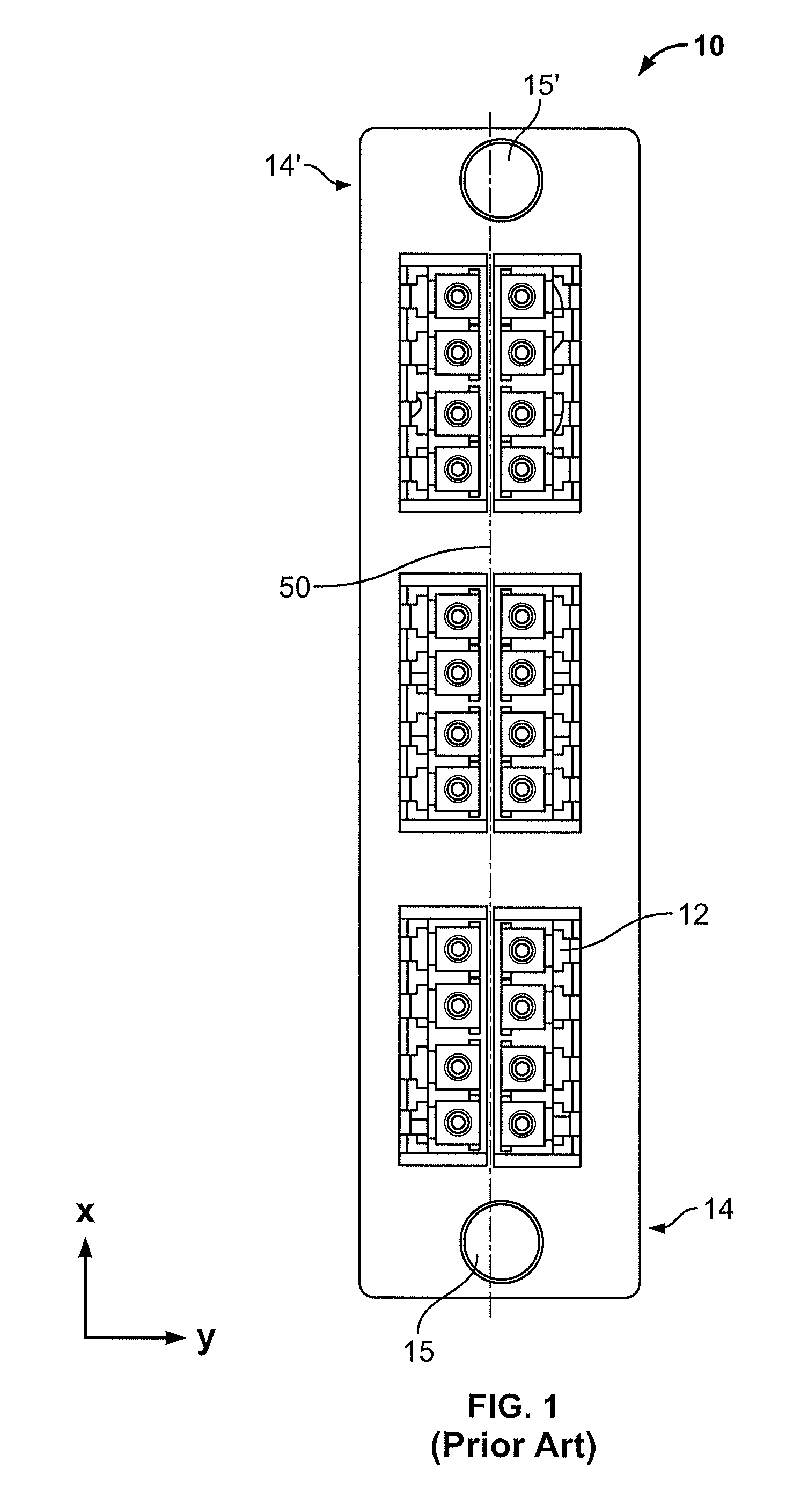
The number of adapters / couplers that may be mounted in a sub-rack enclosure is generally limited by the physical size of the connective devices to be installed, thereby limiting adapter / coupler density.

Method used


Image

  • Mounting panel, system and method for high density fiber optic applications
  • Mounting panel, system and method for high density fiber optic applications
  • Mounting panel, system and method for high density fiber optic applications

Examples


Embodiment Construction

)

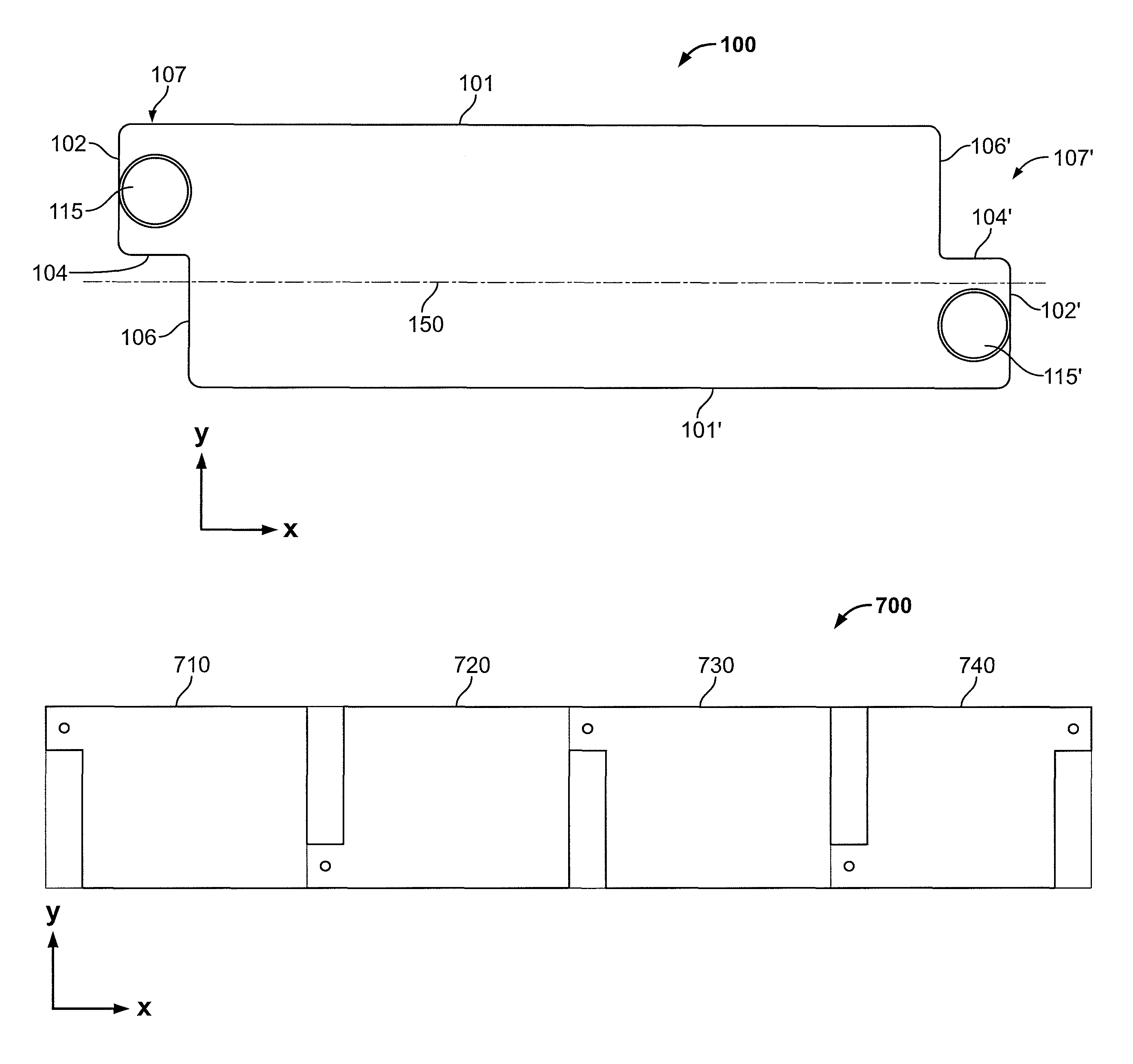
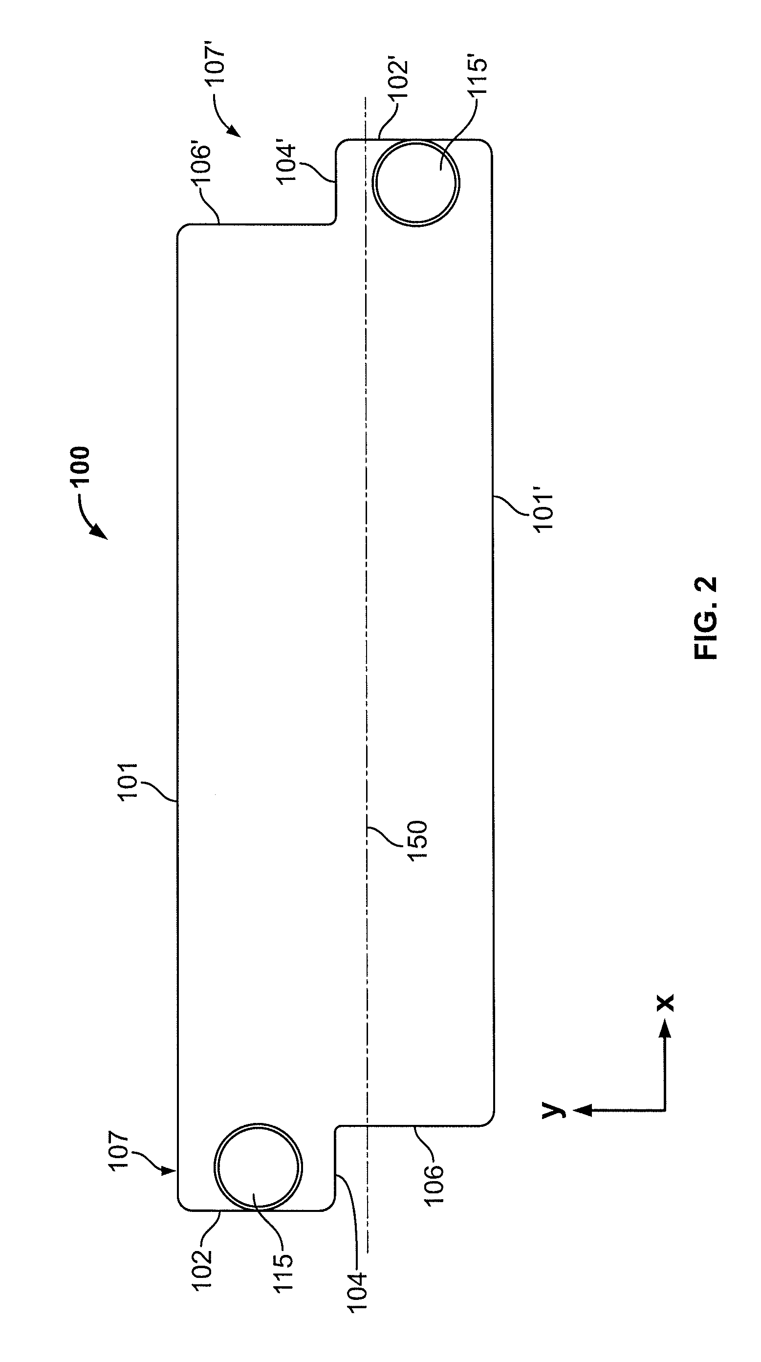
[0022]The present disclosure provides for panels, systems and methods for mounting connective devices for telecommunication equipment effectively within racks or cabinets. An exemplary mounting plate includes a mounting body with at least two L-shaped mounting flanges at opposite ends thereon. The L-shaped mounting flanges are alternatively offset from a centerline. The centerline is defined perpendicular to the portion of the mounting flanges that extends from the mounting plate. An exemplary mounting system includes a plurality of mounting plates with interlocking mounting flanges positioned horizontally on a mounting frame of one standard rack unit (1.75 inches) height. Another exemplary mounting system includes a plurality of mounting plates with overlapping mounting flanges positioned horizontally on a mounting frame, e.g., a mounting frame of one standard rack unit height. Such mounting plates and configurations advantageously facilitate mounting of adapters / couplers and / or b...


PUM

PropertyMeasurementUnit
heightaaaaaaaaaa
densityaaaaaaaaaa
shapeaaaaaaaaaa

Abstract

A mounting plate having at least two L-shaped mounting flanges alternatively offset from a centerline defined to bisect the mounting flanges. A mounting system including a plurality of mounting plates with interlocking mounting flanges positioned horizontally on a mounting frame of one standard rack unit (1.75 inches) height. A mounting system including a plurality of mounting footprints with overlapping fastener flanges positioned horizontally on a mounting frame of one standard rack unit width. A method of mounting plates configured and dimensioned to receive a fiber optic coupler or adapter including a mounting a plurality of plates having at least two L-shaped mounting flanges into a mounting frame such that the mounting flanges of adjacent plates are configured to interlock or overlap.

Description

BACKGROUND[0001]1. Technical Field[0002]This disclosure relates generally to panels, systems and methods for mounting fiber optic connective devices within a rack or cabinet and, more particularly, to mounting panels / systems / methods that allow increased density without sacrificing performance. The disclosed mounting panels / systems / methods advantageously accommodate conventional fiber optic adapters.[0003]2. Background Art[0004]Wired and connected hardware are an integral part of a typical building telecommunications wiring system. In central offices, data centers and other wired buildings, fiber optic patch panels have become a necessary media to route connections between switches, servers, storage devices and the general office area. By “patching,” or temporarily creating a connection between physically mated connectors, it is possible to reconfigure network connections from a central location. As the telecommunication needs of users have increased, the number of devices and the de...

Claims


Application Information

Patent Timeline
Patent Type & Authority Patents(United States)
IPC IPC(8): G02B6/36G02B6/00
CPCG02B6/4452Y10T29/49826G02B6/44526
Inventor MURANO, ADAMRYNASKI, CHESTERHUBBARD, DAVID
Owner CORNING OPTICAL COMM LLC
Learn More