Method for implementing wind energy converting systems

a technology of wind energy and conversion systems, applied in the direction of rotors, vessel construction, marine propulsion, etc., can solve the problems of poor efficiency of adopted solutions, difficult to design and manufacture a wecs fitted with a “de-icing” and/or “anti-icing” system, and difficult to identify regions. , to achieve the effect of short implementation time, easy adaptation and easy implementation

Inactive Publication Date: 2013-03-19
S I SV EL SOC ITAL PER LO SVILUPPO DELLELETTRONICA SPA
View PDF16 Cites 4 Cited by
  • Summary
  • Abstract
  • Description
  • Claims
  • Application Information

AI Technical Summary

Benefits of technology

[0026]In this frame, it is an object of the present invention to provide a method for implementing WECS fitted with anti-icing and de-icing systems which can be implemented easily and which require a relatively short implementation time.
[0028]It is a further object to greatly increase the number of days the WECS can continuously operate in a year, thus avoiding WECS shut-offs due solely to icing or impending icing on the blades.
[0030]It is another object of the invention to obtain the above objects in a simple, practical, inexpensive and efficient manner.

Problems solved by technology

As a matter of facts, the high number of variables involved makes it very difficult to design and manufacture a WECS fitted with a “de-icing” and / or “anti-icing” system, independently of the specific anti-icing and / or de-icing system as applied.
The design and calculation complexity of models simulating the operating conditions of a WECS mostly emerges when calculating the installed power, the absorbed energy and the control of the anti-icing system, the aspects thereof typically lead to poor efficiency of the adopted solutions.
An objective design problem is to determine, in a reliable manner, the power of the anti-icing system to be installed and those regions of the blade surface where said power is to be made available, which regions are very difficult to identify.
As a matter of facts, experience has shown that power calculations obtained with known systems are not enough reliable and lead to considerable inefficiency.
The above described problems represent a clear limit in dimensioning anti-icing and de-icing systems as to their capacity to adapt to different installation sites of the WECS, i.e. to different weather and operating conditions of the WECS.
As far as the applicant knows, the prior art does not provide any known method for implementing a WECS fitted with an anti-icing and de-icing system in accordance with the specific environmental conditions of the site where it is intended to operate.
For example, there are conventional anti-icing and de-icing systems based on the use of electric resistances associated with a portion of the outer surfaces of the rotor blades, which are applied to the outermost blade layer only in a limited region, such as the one across the leading edge, typically for a variable length; this solution provides a low-efficiency of the system.

Method used


Image

  • Method for implementing wind energy converting systems
  • Method for implementing wind energy converting systems
  • Method for implementing wind energy converting systems

Examples


Embodiment Construction

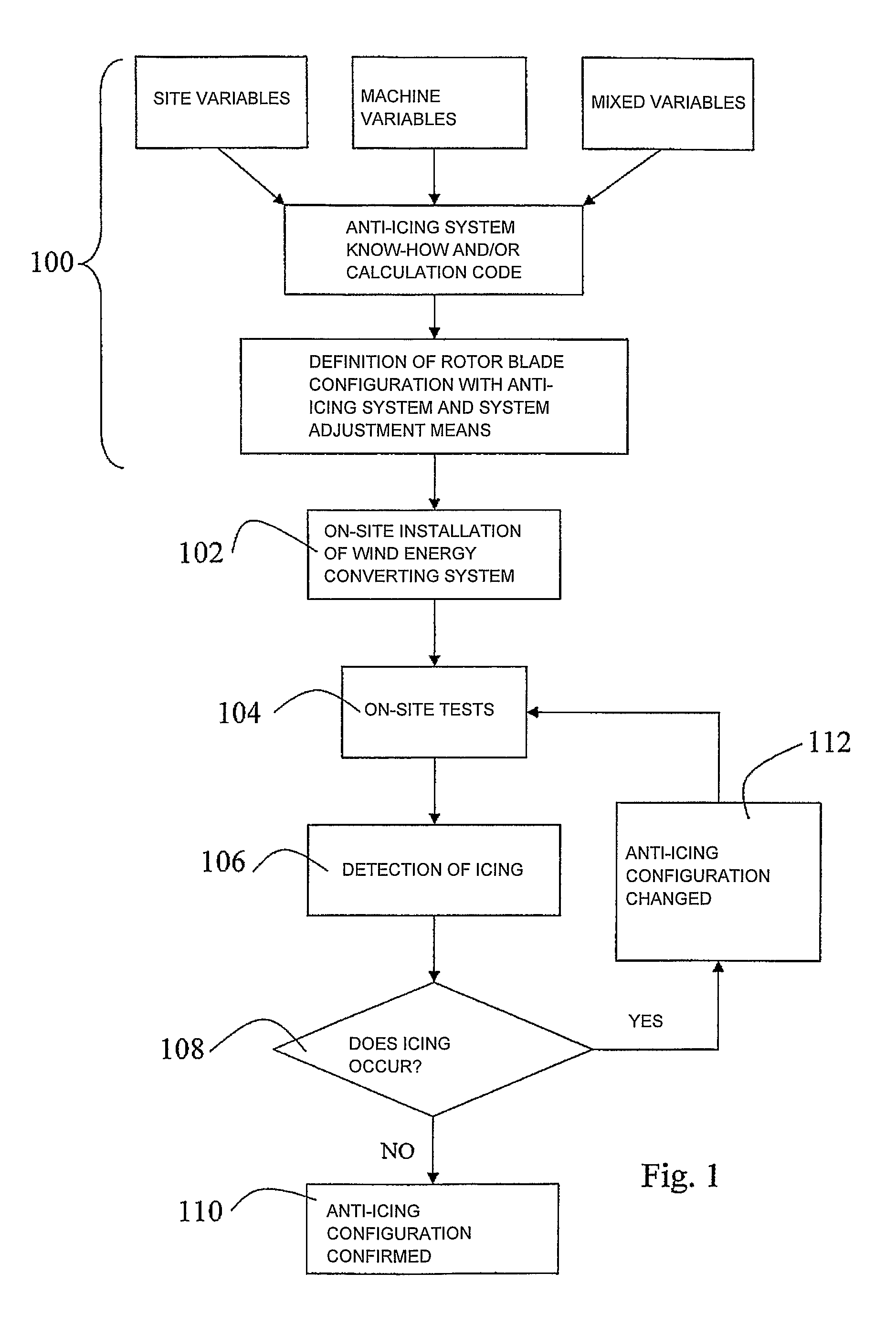
[0040]FIG. 1 shows a flow chart relating to a method for implementing WECS fitted with an anti-icing and de-icing system in accordance with the respective installation sites.

[0041]Said method is based on the following steps:

[0042]a) pre-arranging a wind rotor comprising blades, an anti-icing system, means for adjusting the anti-icing system (step 100);

[0043]b) installing the pre-arranged wind rotor on a test site (step 102);

[0044]c) carrying out at least one operation test of the wind rotor, preferably in critical icing conditions for the location where the WECS is to be installed (step 104);

[0045]d) detecting parameters useful for determining the presence or absence of ice on the blades and / or for establishing the phenomenology under examination, such as temperature and humidity on the blade surface (step 106), through sensors known in the art;

[0046]e) adjusting the anti-icing system by means of its adjustment means (step 112), if ice is detected (step 108);

[0047]f) repeating the p...


PUM

PropertyMeasurementUnit
temperaturesaaaaaaaaaa
temperatureaaaaaaaaaa

Abstract

Wind Energy Converting Systems (WECS) fitted with anti-icing systems are made by using the method according to the invention in the following steps:a) prearranging a wind rotor with blades (5), an anti-icing system, and means (50, 51) for adjusting the anti-icing system;b) installing the prearranged rotor of the WECS on a test site;c) carrying out at least one operation test of the WECS;d) detecting parameters useful for determining the presence or absence of ice on the outer surface (5E) of the blades (5).If the detected parameters do not meet a predetermined target function, the method comprises additional steps of:e) performing an adjustment through said adjustment means (50, 51); repeating the previous steps from c) to e) until no ice is detected on the outer surface (5E) of the blades (5).

Description

BACKGROUND OF THE INVENTION[0001]The present invention relates to a method for implementing Wind Energy Converting Systems (WECS in the following) fitted with anti-icing systems, in accordance with the installation sites where they are meant to operate for producing mechanical work or electric energy.[0002]The present invention also relates to means for implementing said method, to rotor blades fitted with said means, and to a computer program product which can be loaded in the memory of at least one computer and which comprises portions of a computer program for executing at least a portion of said method.[0003]The aforesaid method is particularly suited to being applied to WECS provided with an anti-icing system, as described in the international patent application WO 2004 / 036038, being equivalent to the Italian patent application No. TO 2002A000908 in the name of the same Applicant of the present application.[0004]For the sake of brevity, the contents of said international and It...

Claims


Application Information

Patent Timeline
Patent Type & Authority Patents(United States)
IPC IPC(8): F03D1/00
CPCF03D7/042F03D11/0025F05B2270/323Y10T29/49316Y02E10/722Y02E10/723F05B2270/325F03D80/40Y02E10/72
Inventor BATTISTI, LORENZO
Owner S I SV EL SOC ITAL PER LO SVILUPPO DELLELETTRONICA SPA
Why Eureka
Try Eureka