Ear canal pressurization device

a pressurizing device and ear canal technology, applied in vibration massage, application, diagnostic recording/measuring, etc., can solve the problems of system and misinterpretation, noise may be detected, and none of these systems meet all of the above stated requirements, so as to reduce the need for acoustical damping in the air line, the effect of unlimited and maintenance free life span

Active Publication Date: 2013-03-19
MICRO AUDIOMETRICS CORP
View PDF3 Cites 12 Cited by
  • Summary
  • Abstract
  • Description
  • Claims
  • Application Information

AI Technical Summary

Benefits of technology

[0007]A disclosed embodiment of the ear canal pressurization device can be driven by a DC voltage to provide a static ear canal pressure, and can be driven by an AC voltage to produce an alternating ear canal pressure function. The embodiment utilizes Boyle's gas law principle to vary ear canal air pressure by changing the volume of a flexible chamber coupled to an ear canal. The volume of said flexible chamber is varied via a moving magnet linear motor driven by a forcer in one direction to compress said flexible chamber, which decreases its internal volume to increase pressure, or in the opposite direction to expand said flexible chamber, which increases its internal volume to decrease pressure. The device operates quietly to avoid interference with AAI measurement, and should have a long and maintenance free life span.
[0009]In another embodiment of the invention, the ear canal pressurization device is utilized with or without venting, but with no valve. This embodiment would be less expensive to implement, would obviate the need for valve control, and would be suitable for tympanometric screening tests.
[0022]In summary, this disclosure provides several advantages for the implementation of an ear canal pneumatic system suitable for use during AAI testing. The device operates quietly, which minimizes the need for acoustical damping in the air line. The device requires only a DC or AC driving voltage in place of a more complicated drive means (e.g., stepper motor control and gear drive). The device produces pressure changes by increasing or decreasing the volume of a flexible chamber, and may be used to set static ear canal pressure or to generate a variety of ear canal pressure functions. The ear canal pressurization device is relatively simple to implement and should have a virtually unlimited and maintenance free life span, determined primarily by the properties of the material used for the first and second flexible chambers.

Problems solved by technology

Noise produced by the pressure generation mechanism must be minimal, or the noise may be detected by the AAI measurement system and be misinterpreted as an admittance change, particularly during acoustic reflex testing.
None of these systems meet all of the above stated requirements.
They require a stepper motor controller, acoustic damping in the air line to reduce stepper motor noise, and are prone to leakage due to plunger seal wear.
Oscillating diaphragm pumps also require tuning, since they perform optimally at a specific drive frequency, and this necessitates a more complicated calibration procedure.
These pumps require acoustic damping in the air line and they also require periodic replacement of the tubing, which is constantly stressed by the roller providing the “squeeze”.
Additionally, peristaltic pumps are prone to leaks when the spring force which holds the roller against the flexible tubing fails to fully pinch off the tubing.
Another disadvantage of piezo electric motors is that they require high frequency, high voltage driving signals and relatively sophisticated controllers.

Method used


Image

  • Ear canal pressurization device
  • Ear canal pressurization device
  • Ear canal pressurization device

Examples


Embodiment Construction

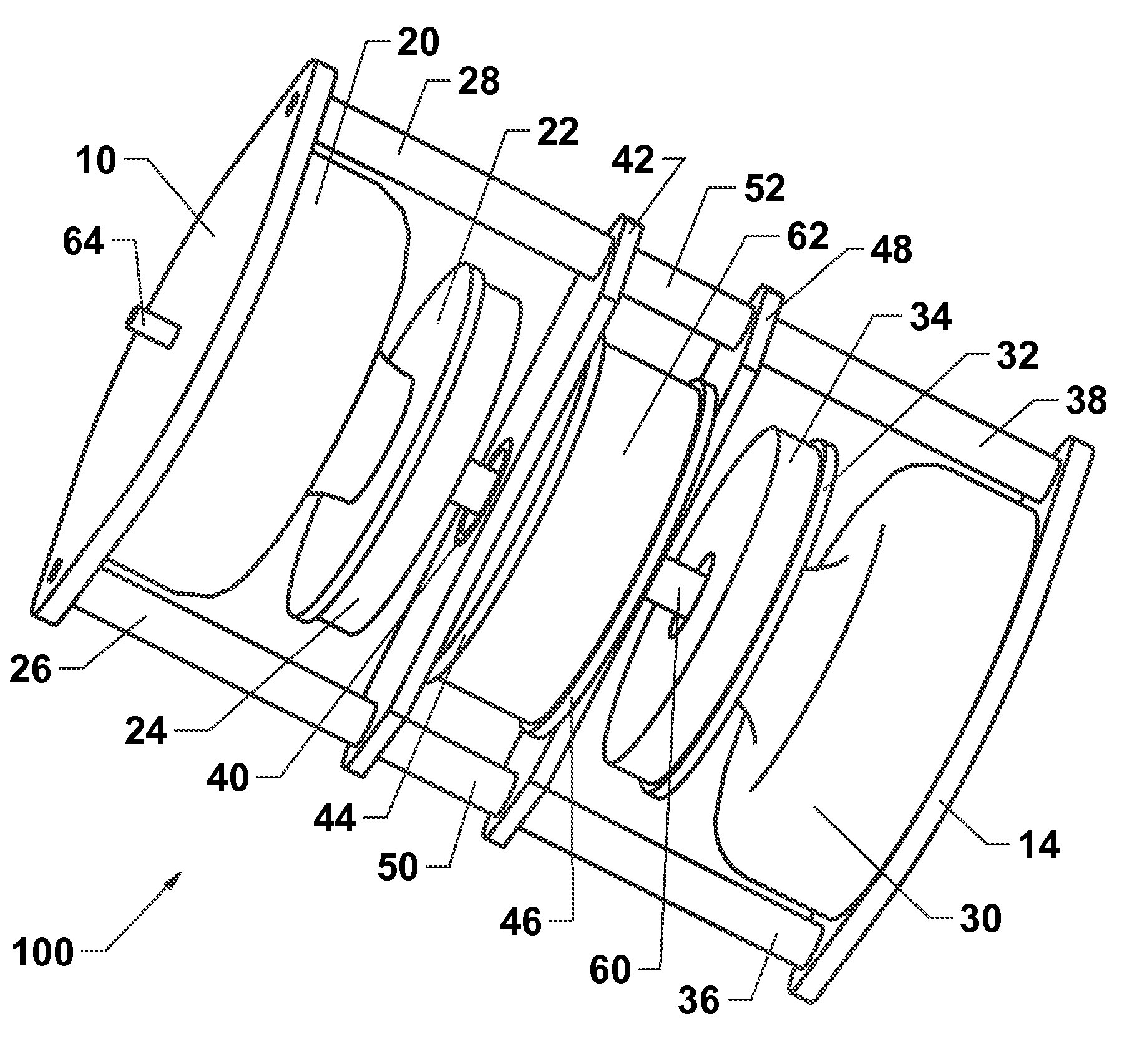
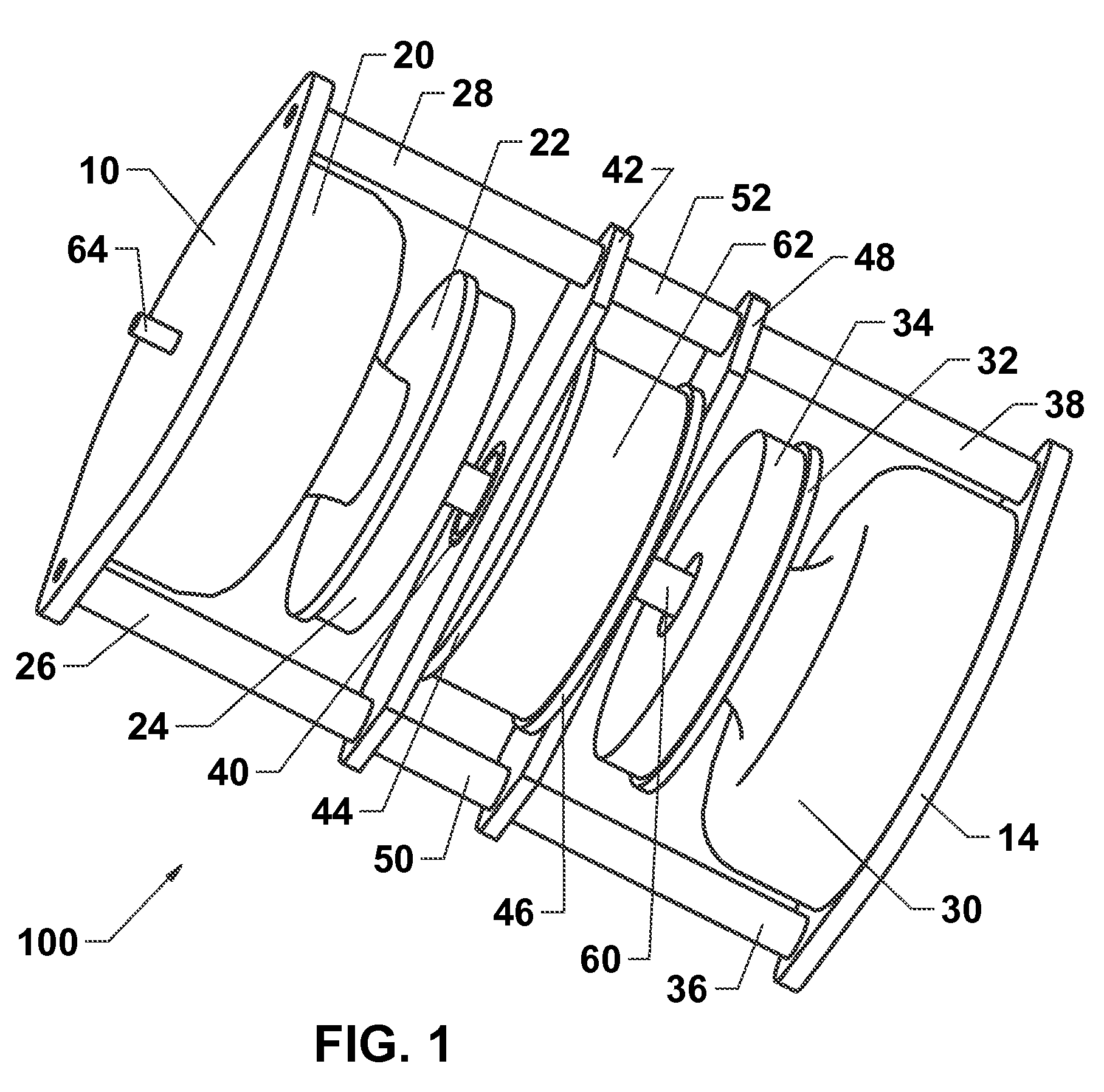
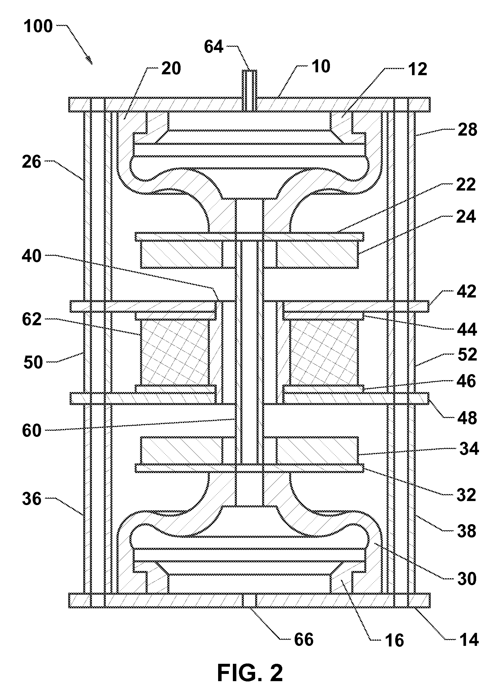
[0033]A preferred embodiment of an ear canal pressurization device 100 is shown in FIGS. 1, 2, and 6.

[0034]The forcer assembly 108 includes a first forcer assembly mounting bracket 42, a first forcer assembly washer 44, a forcer assembly core 40, a second forcer assembly washer 46, and a second forcer assembly mounting bracket 48. Said first and second forcer assembly mounting brackets are preferably made of non-ferromagnetic material (e.g., plastic or aluminum) and, along with forcer assembly spacers 50 and 52, provide mounting for the forcer assembly. The forcer assembly core 40 preferably includes a rigid length of cylindrical, hollow, ferromagnetic material (e.g., iron) with inner diameter sufficiently large to allow a chamber link 60 to pass through without touching the forcer assembly core 40. Said forcer assembly core has a reduced diameter at one end to receive the first forcer assembly washer 44 and first forcer assembly mounting bracket 42, which are press fit onto a first...


PUM


Abstract

An ear canal pressurization device optimized for aural acoustic immittance testing is disclosed. Changes in volume of a first flexible chamber, due to motor movement, produce changes in ear canal pressure based on Boyle's law. A vent may be opened to allow ear canal pressure to gently equalize to ambient air pressure or to generate ear canal pressure sweeps free of pressure baseline offset. The vent may be closed to set a static ear canal pressure or to generate ear canal pressure sweeps with an incidental baseline offset. The vent may be controlled to generate ear canal pressure sweeps with an intended baseline offset. The device produces ear canal pressure proportional to drive voltage, so any desired pressure versus time function can be generated by applying a coil driving voltage with the appropriate amplitude versus time function.

Description

FIELD OF THE INVENTION[0001]This invention generally relates to an ear canal pressurization device optimized for use during aural acoustic immittance testing. The disclosed device is a dual flexible chamber apparatus driven by a moving magnet linear motor. The device operates quietly and can generate a static ear canal pressure (below or above atmospheric) when driven by DC voltage or an alternating ear canal pressure function when driven by an AC voltage.BACKGROUND OF THE INVENTION[0002]The status of the middle ear system (tympanic membrane and ossicular chain) may be clinically ascertained by measuring aural acoustic immittance (AAI) at the entrance to the ear canal (immittance refers to either admittance or impedance). Typically, AAI measures are made as air pressure in the ear canal is parametrically varied below or above atmospheric pressure. AAI measures are obtained by sealing the tip of a probe, surrounded by a flexible cuff, in the opening to an ear canal, and the probe inc...

Claims


Application Information

Patent Timeline
Patent Type & Authority Patents(United States)
IPC IPC(8): A61B5/00A61F11/00A61H1/00A61F11/06A61B5/12
CPCA61B5/121A61H21/00A61H9/005A61H23/0218A61H2201/5071A61H2205/027
Inventor KELLER, JAMES E.
Owner MICRO AUDIOMETRICS CORP
Why Eureka
Try Eureka