Security closure for cam and groove hose coupling

a technology of cam and groove hose and security closure, which is applied in the direction of mechanical equipment, locking devices, transportation and packaging, etc., can solve the problems of exposed lock and cam lever arms, which are prone to being cut, and cannot be tampered with

Active Publication Date: 2013-03-26
KASTALON
View PDF39 Cites 3 Cited by
  • Summary
  • Abstract
  • Description
  • Claims
  • Application Information

AI Technical Summary

Benefits of technology

[0008]Toward these and other ends, the security closure system of the invention comprises a first part that is a terminal male-component that terminates the hose connector connected to the outlet of a storage tank whose contents are to be periodically pumped out. The male-component is provided with an outer, circumferential annual groove for reception therein of camming elements of camming arms, and with a terminal projecting tongue provided with an opening or hole for receiving a locking device, such as a padlock. The male-component is further provided with an enlarged mounting flange for mounting the male-component to a wall of the storage tank or to a bulkhead adjacent the storage tank. The security closure system also comprises a second part, which is a female closure cap that matingly receives therein the first male-component. The closure cap has a slot for passing therethrough the tongue of the first male-component, whereby a padlock or other lock may be used for locking the cap in place over the first male-component. The closure cap is also provided with a pair of parallel, upstanding partitions or walls sandwiching therebetween the projecting tongue of the first male-component protruding through the slot of the closure cap. These partitions project a sufficient height above, and extend a sufficient length along, the protruding tongue so as to prevent access thereto and to the locking device inserted through the opening of the tongue, whereby access thereto is denied and the tampering thereof via saws, and the like, is prevented. The closure cap is also, preferably, provided with camming arms with distal camming elements for reception in the annular groove of the first male-component, in the conventional manner, as described hereinabove. In order to further ensure a tamper-proof security cap, a loosely-mounted shaft or dowel pin is provided that may be also be freely rotatable in a hole or opening of the cap, whereby if a saw or cutting tool were to try to cut open the cap, it would engage this freely rotatable bolt or shaft, which would render any cutting by the saw useless.

Problems solved by technology

A problem exists with these prior-art closure caps in that they are not tamper-proof.
It is a considerable problem in all industries that use storage tanks for storing fluid contents that are periodically pumped out to a transport tank, train car, or the like, that these camming arms, no matter how well protected from being accessed, are prone to attack by the use of bolt cutters, saws and other such devices, thus allowing ready access to and theft of the contents of the storage tank.
Both the exposed lock and the cam lever arms, however, are prone to being cut by the use of bolt cutters, saws and other such devices.

Method used


Image

  • Security closure for cam and groove hose coupling
  • Security closure for cam and groove hose coupling
  • Security closure for cam and groove hose coupling

Examples


Embodiment Construction

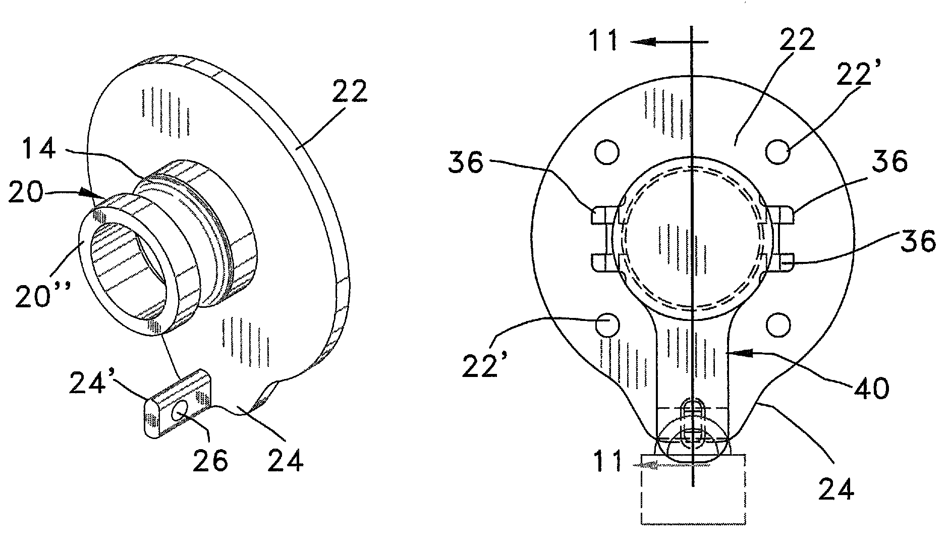
[0052]Referring now to the drawings in greater detail, there is shown in FIGS. 2-11, there is shown a first embodiment of the security closure cap device of the invention. In the first embodiment, the outlet coupler 20 extending from the storage tank (not shown) is a male component as shown in FIGS. 2-4, and is made up of a main male component proper 20′ with an outer circumferential, annular groove 14 for receiving camming members of camming arms of the mating female closure cap discussed hereinbelow. The male outlet coupler 20 also has an enlarged mounting flange element 22 integrally connected at one end of the male coupler proper 20′ closest to the storage tank when mounted for use with a storage tank, which male coupler proper also has an internal-thread section 22″, either of flange or pipe male or female threads, at its end adjacent the flange for receiving a hose connection associated with the storage tank. The mounting flange-element 22 is affixed to a wall of the storage t...


PUM


Abstract

A security closure system for terminating the hose-connector connected to the outlet of a storage tank whose contents are to be periodically pumped out. A first male-outlet component is provided with an outer, circumferential annual groove for reception therein of camming elements of camming arms, and has a terminal projecting tongue provided with an opening or hole for receiving a locking device, such as a padlock. The male-component is further provided with an enlarged mounting flange for mounting the male-component to a wall of the storage tank or to a bulkhead adjacent the storage tank. The security closure system also comprises a second female part, which is a female closure cap that matingly receives therein the first male-component. The closure cap has a slot for passing therethrough the tongue of the first male-component, whereby a padlock or other lock may be used for locking the cap in place over the first male-component. The closure cap is also provided with a pair of parallel, upstanding partitions or walls sandwiching therebetween the projecting tongue of the first male-component protruding through the slot of the closure cap. These partitions project a sufficient height above, and extend a sufficient length along, the protruding tongue so as to prevent access thereto and to the locking device inserted through the opening of the tongue, whereby access thereto is denied and the tampering thereof via saws, and the like, is prevented. Additional pins or rods are provided for additional tamper-proof resistance to cutting.

Description

CROSS REFERENCE TO RELATED APPLICATION[0001]This is a continuation-in-part of application Ser. No. 12 / 545,988, filed on Aug. 24, 2009, now U.S. Pat. No. 8,286,829.BACKGROUND OF THE INVENTION[0002]The present invention is directed to a secure-closure cap for a cam-and-groove hose coupling. Cam-and-groove hose couplings are used ubiquitously in many environments and areas for safely coupling together the ends of hoses and other connectors. A typical cam-and-groove coupling consists of an outer annular groove in the outer circumference of a male end of a first hose-connector, and a pair of diametrically-opposed, pivotal camming arms mounted by a female end of a second hose-connector. Each camming arm has a cam-element at a free, cantilevered end thereof which cooperates and extends into the interior of the female end of the second hose-connector. The cam-elements are receivable in the outer circumferential annular groove of the male end of the first hose connector when the male end is ...

Claims


Application Information

Patent Timeline
Patent Type & Authority Patents(United States)
IPC IPC(8): B65D55/14B65D45/20
CPCF16L55/1157
Inventor DEMENT, R. BRUCE
Owner KASTALON
Why Eureka
Try Eureka