ECG monitoring electrode

a technology of ecg and electrode, which is applied in the field of improved medical electrodes, can solve the problems of emotional distress of patients, time-consuming procedures, and extraneous signals, and achieve the effect of avoiding the cost, size and power-consuming characteristics inherent in mechanical drive tools

Active Publication Date: 2013-03-26
TIEGS MARK
View PDF8 Cites 50 Cited by
  • Summary
  • Abstract
  • Description
  • Claims
  • Application Information

AI Technical Summary

Benefits of technology

[0022]The rotating step may include providing an electrode with an electrode stud having an external multi-faceted configuration, providing a drive tool, the drive tool having a first end with a bore sized and configured to matingly engage the electrode stud external configuration, placing the drive tool over the electrode stud such that the first end of the electrode stud is inserted in the drive tool bore, and rotating the tool in a first direction and a second opposite direction. In the preferred embodiment, the drive tool is hand-operated which avoids the cost, size and power consuming characteristics inherent in mechanical drive tools.
[0025]Another aspect of the invention is a kit including a plurality of electrodes carried on a backing member, each electrode including a securing element having a first surface and an opposed second surface, the securing element having a first aperture therethrough, the first aperture extending from the first surface to the second surface, a snap-cover having a first surface and a second surface, at least a portion of the first surface being coupled to the second surface of the securing element, the snap-cover having a second aperture therethrough, an electrode stud having a first end and a second end, the first end of the electrode stud being rotatably retained within the snap-cover aperture, an electrode element having a first surface and a second surface, the first surface being coupled to the second end of the electrode stud, and abrading means coupled to the second surface of the electrode element. The kit further including a drive tool having a first end sized and configured to engage the first end of the electrode stud. In the preferred embodiment, the drive tool is hand-operated which avoids the cost, size and power consuming characteristics inherent in mechanical drive tools.

Problems solved by technology

This movement can cause extraneous signals, shifting the desired signal baseline.
This procedure is not only time consuming, but may be painful to the patient.
The processes may also cause emotional distress to the patient as the patient views the skin abrading procedure.

Method used


Image

  • ECG monitoring electrode
  • ECG monitoring electrode
  • ECG monitoring electrode

Examples


Embodiment Construction

[0034]Although the disclosure hereof is detailed and exact to enable those skilled in the art to practice the invention, the physical embodiments herein disclosed merely exemplify the invention which may be embodied in other specific structures. While the preferred embodiment has been described, the details may be changed without departing from the invention, which is defined by the claims.

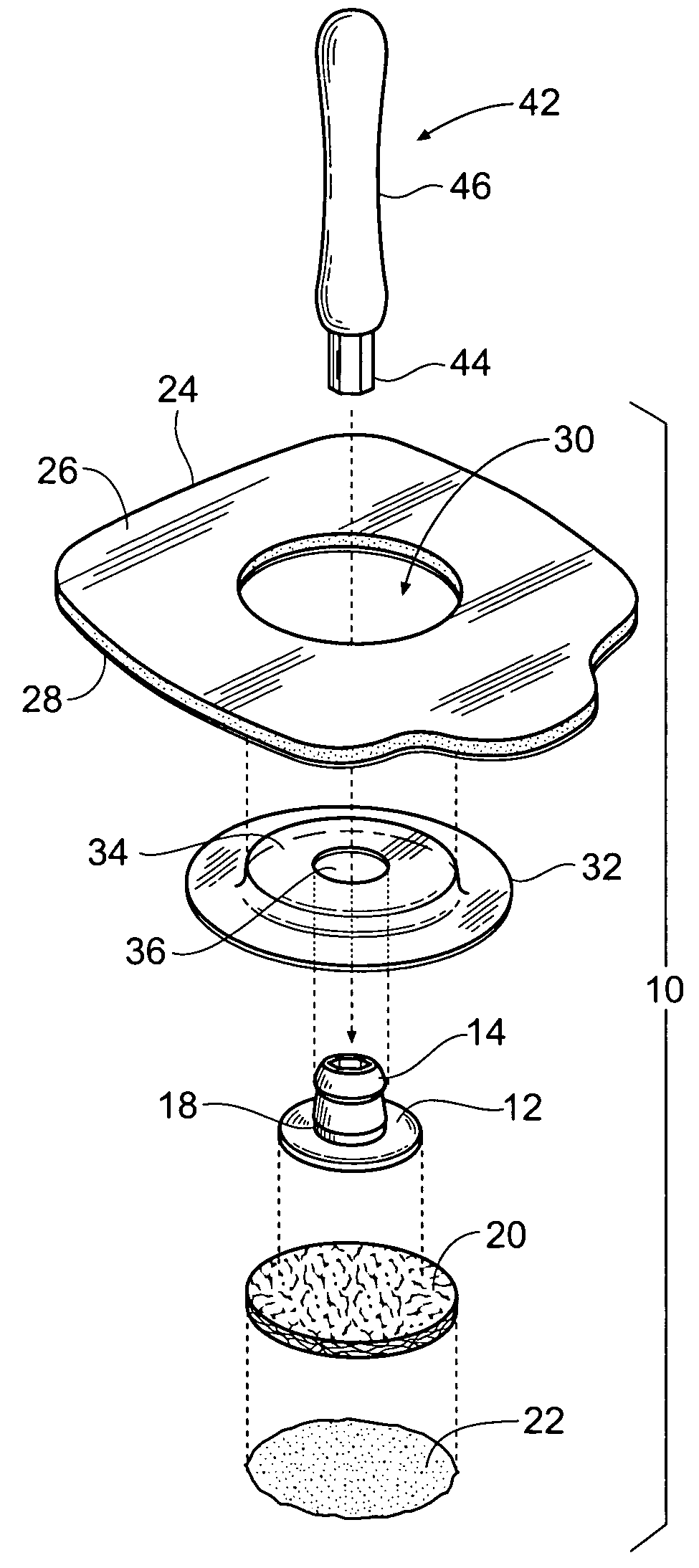
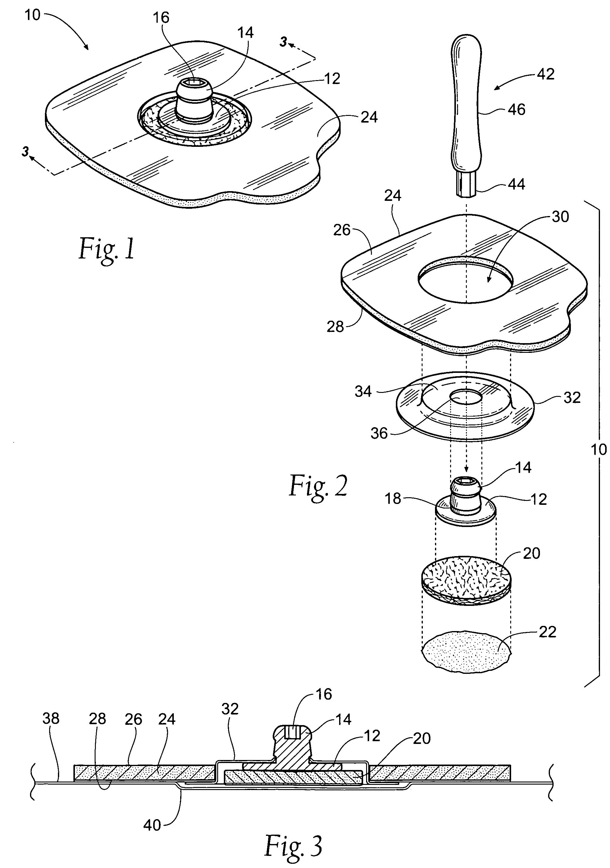
[0035]FIG. 1 shows an electrode assembly 10 according to the present invention. As shown in FIG. 2, the electrode assembly preferably includes a securing element 24, a snap-cover member 32, an electrode stud 14, and electrode element 12, an abrasive pad 20, and an electrolyte gel 22.

[0036]As shown in FIG. 1 the electrode assembly 10 preferably includes an electrode element 12 coupled to an electrode stud 14. In the preferred embodiment the electrode element 12 and the electrode stud 14 are integrally formed. However, it is contemplated that these elements 12,14 could be formed separately and coupl...


PUM


Abstract

A self-prepping ECG electrode assembly is provided. The electrode assembly includes an electrode element, an electrode stud, an abrasive member, an electrolyte gel, a cover member and a securing member. The electrode element and electrode stud are adapted to be rotatable within the electrode assembly. The electrode assembly may be used with a drive tool. The electrode assembly may be placed on the skin of a patient. The skin of the patient may be prepped for an ECG by inserting the drive tool into a bore formed in the electrode stud and turning the drive tool to achieve an oscillating rotation. In this manner the abrasive pad preps the patient's skin for the ECG procedure.

Description

RELATED APPLICATIONS[0001]This application claims the benefit of U.S. Provisional Patent Application Ser. No. 61 / 123,095, filed 4 Apr. 2008 and entitled “ECG Monitoring Electrode”BACKGROUND OF THE INVENTION[0002]This invention related to an improved medical electrode which provides the capability to manually abrade the epidermal layer of the skin in contact with the electrode.[0003]Disposable electrodes applied to the skin of a patient are used to monitor the electrical activity of bodily functions. Electrocardiogram or ECG electrodes are positioned on a patient's body to gather biopotential electrical signals generated by the heart. These signals are generally transmitted to a monitor that produces a visual representation of the patient's heart condition.[0004]The strength and accuracy of the signals from the ECG electrodes to the monitor is dependent on motion artifacts caused by the movement of the patient's skin relative to the electrode. This movement can cause extraneous signa...

Claims


Application Information

Patent Timeline
Patent Type & Authority Patents(United States)
IPC IPC(8): A61B5/0408A61B5/0416A61B5/274
CPCA61B5/0416A61B2562/0217A61B5/274
Inventor TIEGS, MARKARNDT, EDWARD
Owner TIEGS MARK
Why Eureka
Try Eureka