
Unified connector architecture

a technology of connectors and connector modules, applied in the field of unified connector architecture, can solve the problems of limiting the ability of mobile computers to have a full complement of mobile computer interfaces, and the rear peripheral interface panel on many desktop systems has unfortunately grown in siz

Active Publication Date: 2013-03-26
INTEL CORP
View PDF37 Cites 7 Cited by
  • Summary
  • Abstract
  • Description
  • Claims
  • Application Information

AI Technical Summary

Benefits of technology

The present invention relates to a unified connector architecture for computer platforms that aims to solve the problem of multiple host controllers and associated hardware interfaces required to connect peripherals to a computer platform. The invention provides a unified connector architecture that reduces the amount of motherboard and case real estate required to house all the necessary hardware interfaces. The invention includes a system-level implementation of a unified connector architecture that includes a CPU, system memory, and discrete graphics controller, among others. The invention also includes a unified I / O complex that houses one or more I / O host controllers and allows for communication with I / O peripherals attached to the computer system. The invention provides a solution for reducing the size of the rear peripheral interface panel on mobile computers and making the case of desktop systems more compact. The technical effects of the invention include reducing the size of the connector system and making it more efficient in terms of motherboard and case real estate.

Problems solved by technology

This has limited the ability for mobile computers to have a full complement of these interfaces and the rear peripheral interface panel on many desktop systems has unfortunately grown in size as well.

Method used


Image

  • Unified connector architecture
  • Unified connector architecture
  • Unified connector architecture

Examples


Embodiment Construction

[0009]Embodiments of a system, device, and method to implement a unified connector architecture on a computer platform are described. In the following description, numerous specific details are set forth. However, it is understood that embodiments may be practiced without these specific details. In other instances, well-known elements, specifications, and protocols have not been discussed in detail in order to avoid obscuring the present invention.

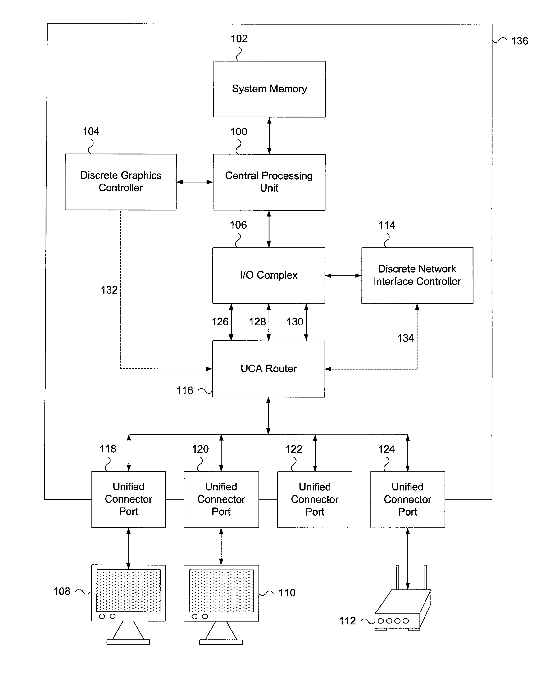
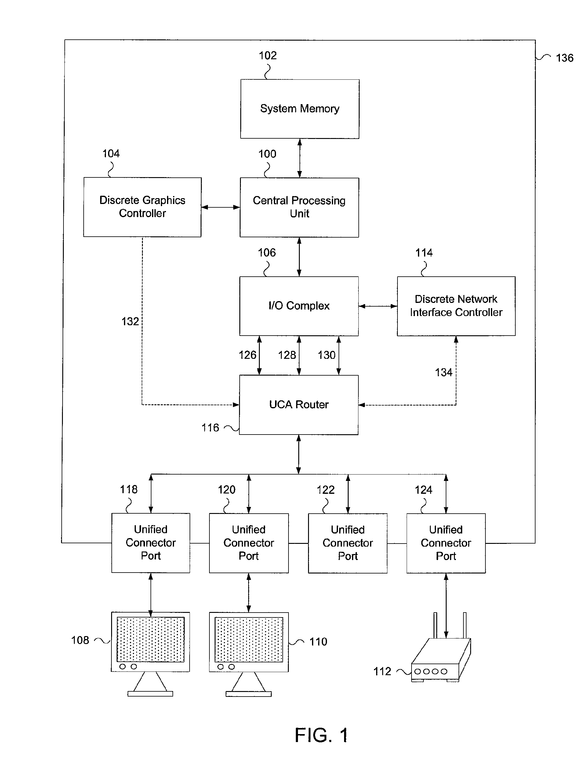
[0010]FIG. 1 describes one embodiment of a system-level implementation of a unified connector architecture. In many embodiments, the system includes one or more processors, such as central processing unit (CPU) 100. In different embodiments, CPU 100 may include one core or multiple cores. In some embodiments, the system is a multiprocessor system (not shown) where each of the processors has one core or multiple cores.

[0011]CPU 100 is coupled to system memory 102 through one or more high speed links (i.e. interconnects, buses, etc). System ...


PUM


Abstract

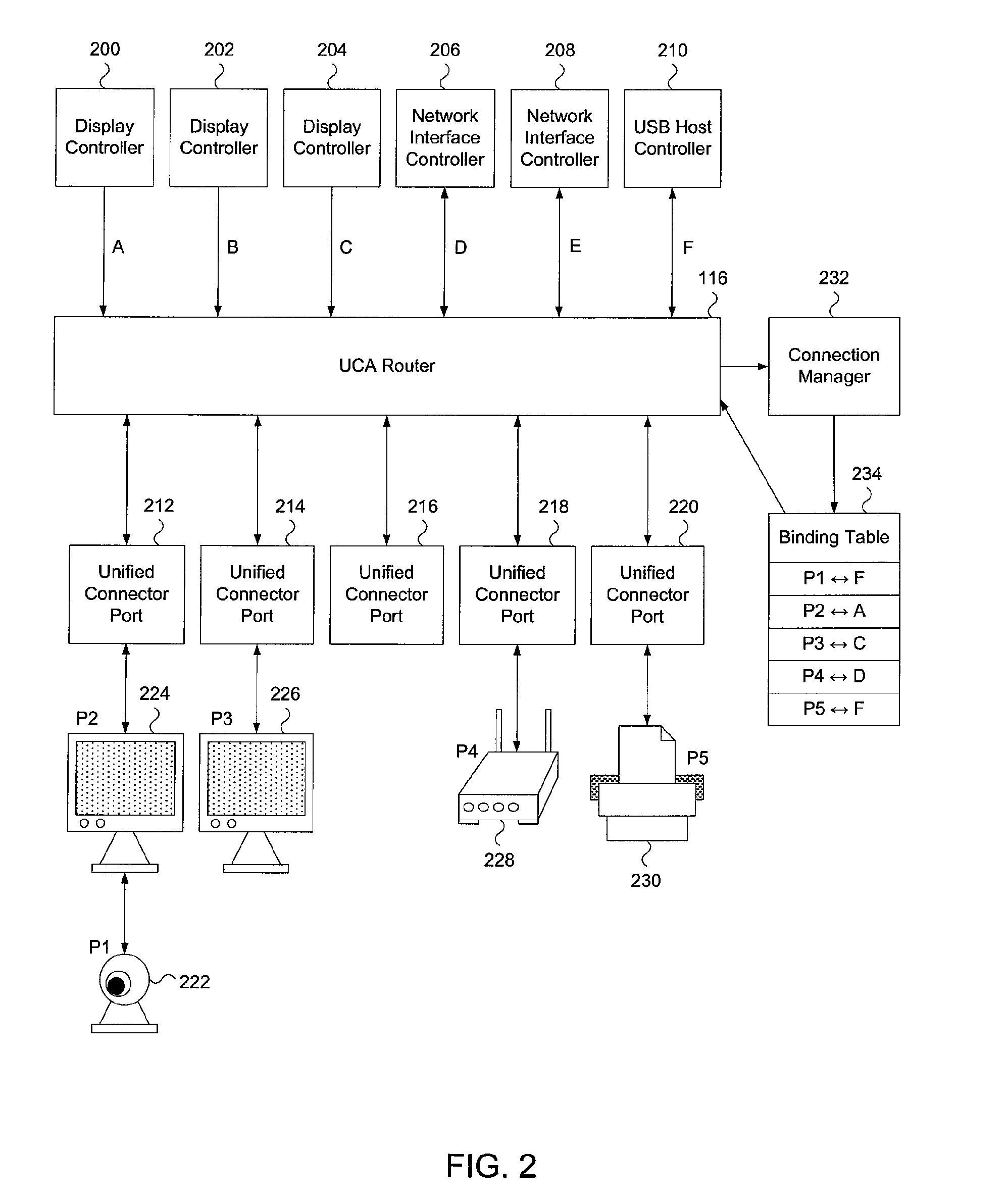
A system, device, and method are disclosed. In one embodiment the system includes a first host controller that utilizes a first protocol. The system also includes a second host controller that utilizes a second protocol. The system also includes a unified connector port. Finally, the system includes a router that is coupled to the first host controller, the second host controller, and the unified connector port. The router is functionally capable of encapsulating a physical layer packet from the first host controller into a first unified connector protocol frame and then transmits the new first frame to the unified connector port. The router is also capable of encapsulating a physical layer packet that it receives from the second host controller into a second unified connector protocol frame and then transmits the second frame to the unified connector port. The first and second protocols are not the same protocol.

Description

FIELD OF THE INVENTION[0001]The invention relates to the implementation of a unified connector architecture across a computer system.BACKGROUND OF THE INVENTION[0002]Current computer platform architecture has a variety of host controllers to implement a number of different types of I / O between computer platforms and peripherals that are connected to the platforms. For example, a graphics host controller potentially has analog and digital ports with corresponding connection interfaces (i.e. the plugs at the ends of the cables connecting a display device to a computer platform. Local area network controllers within the platform commonly have one or more Ethernet jacks. The Universal Serial Bus (USB) subsystem has a number of associated USB plug interfaces. IEEE 1394 Firewire also may have one or more plug interfaces. The list of separate and distinct ports and the associated hardware interfaces to plug peripherals into a computer platform go on and on. Computer platforms with all of t...

Claims


Application Information

Patent Timeline
Patent Type & Authority Patents(United States)
IPC IPC(8): G06F15/16G06F13/38
CPCG06F13/387G06F13/14H04L9/40
Inventor CHANDRA, PRASHANT R.BHATT, AJAY V.
Owner INTEL CORP
Learn More