Remote operation system

a remote operation and system technology, applied in the field of remote operation systems, can solve problems such as confusion and inconvenience for users

Inactive Publication Date: 2013-03-26
FUJITSU COMPONENENT LTD
View PDF10 Cites 32 Cited by
  • Summary
  • Abstract
  • Description
  • Claims
  • Application Information

AI Technical Summary

Benefits of technology

[0008]It is an object of the present invention to provide a remote operation system that can avoid key input that a user does not intend.
[0010]With the above arrangement, it is possible to make the state of the keyboard of the client identical with that of the keyboard of the server, and avoid the key input that the user does not intend.
[0012]With the above arrangement, it is possible to make the state of the keyboard of the client identical with that of the keyboard of the server, and avoid the key input that the user does not intend.

Problems solved by technology

However, when the user of the client starts a remote operation, a state of the keyboard of the client may be not identical with a state of the keyboard of the server.
When the state of the keyboard of the client is not identical with the state of the keyboard of the server, and the user of the client executes the key input, input letters are different from letters displayed as the screen data of the server, thereby impairing usability.
However, when the “Caps Lock” key of the server is off, a lower-case letter of the alphabet is displayed as the screen data of the server, and hence confusion is given to the user.

Method used


Image

  • Remote operation system
  • Remote operation system
  • Remote operation system

Examples


first embodiment

(First Embodiment)

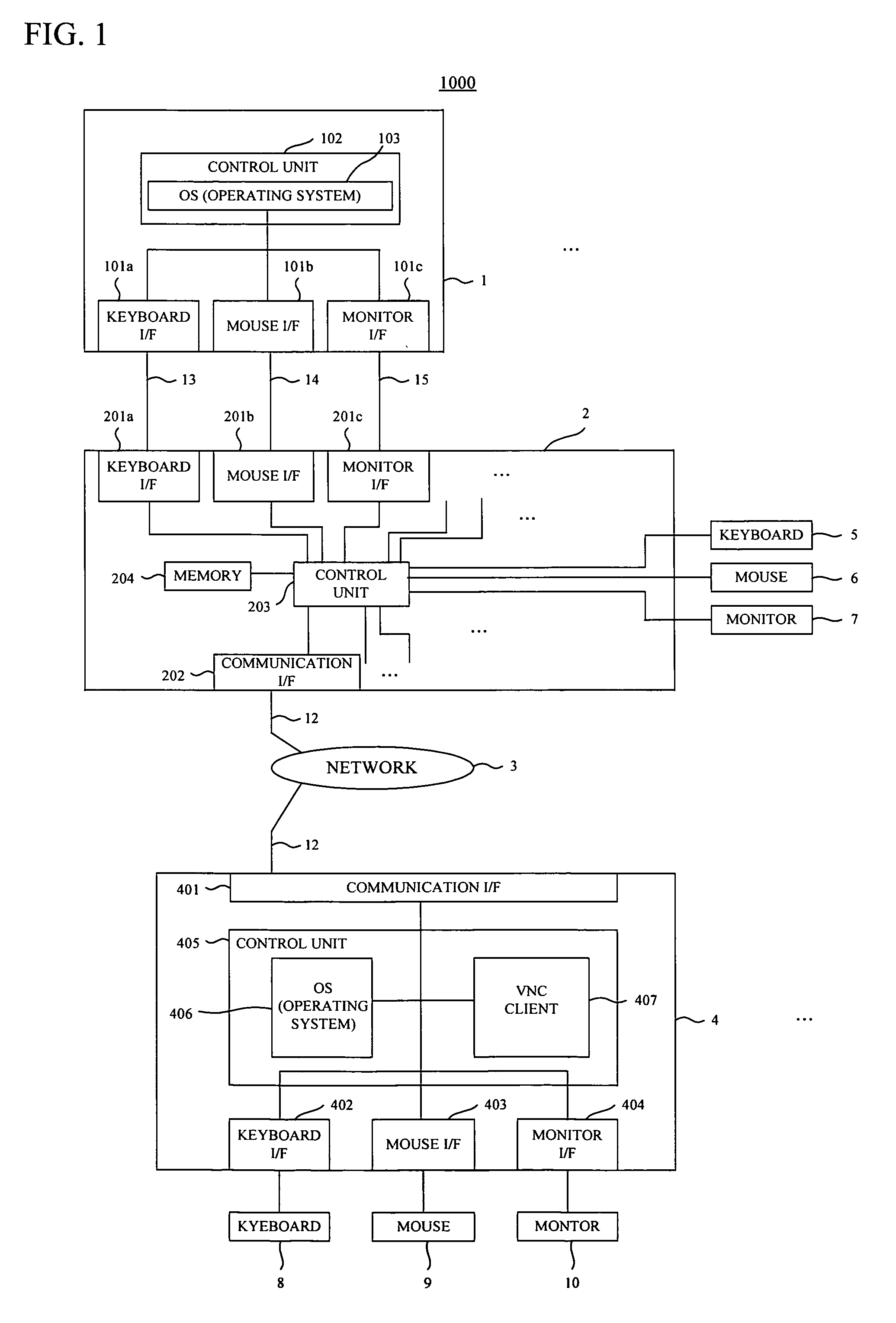
[0022]FIG. 1 is a schematic diagram showing the configuration of a remote operation system according to a first embodiment.

[0023]In FIG. 1, a remote system 1000 includes a server 1, a KVM switch 2, and a client 4. The server 1 is connected to the KVM switch 2 via cables 13 to 15. The client 4 is connected to the KVM switch 2 via a network 3 and LAN cables 12. Although the remote system 1000 includes the server 1 and the client 4 in FIG. 1, the remote system 1000 may include a plurality of servers and clients.

[0024]The server 1 includes: a keyboard interface (I / F) 101a to which the cable 13 is connected; a mouse interface (I / F) 101b to which the cable 14 is connected; a monitor interface (I / F) 101c to which the cable 15 is connected; and a control unit 102 that controls the entire server 1. The control unit 102 includes an OS (operating system) 103. Although the OS 103 is Windows (registered trademark), UNIX (registered trademark), MAC OS (registered trademark), or ...

second embodiment

(Second Embodiment)

[0056]In the above-mentioned first embodiment, the states of the LEDs on the keyboard 8 of the client 4 is changed according to the states of the LEDs on the keyboard 5 of the server 1. On the contrary, in the present embodiment, the states of the LEDs on the keyboard 5 of the server 1 is changed according to the states of the LEDs on the keyboard 8 of the client 4.

[0057]The configuration of the remote operation system according to the second embodiment is the same as that of the remote operation system according to the first embodiment, and hence a description thereof is omitted.

[0058]FIGS. 6A and 6B are flowcharts showing a process executed with the remote operation system according to the second embodiment. In the present flowcharts, the CPU 121 properly reads out the OS 406 or the VNC client 407 from the HDD 424, and starts up the OS 406 or the VNC client 407, so that the process executed with the OS 406 or the VNC client 407 is achieved.

[0059]First, when the ...


PUM


Abstract

A remote operation system has a server, a client to which a first keyboard is connected, and a KVM switch connected to the server, the client and a second keyboard, the KVM switch including: an acquisition portion that acquires a state of the second keyboard; and the client including: a reception portion that receives a state of the first keyboard, and the state of the second keyboard from the KVM switch; a determination portion that determines whether the state of the first keyboard is identical with the state of the second keyboard; and a transmission portion that transmits information which makes the state of the first keyboard identical with the state of the second keyboard, to the first keyboard when the state of the first keyboard is not identical with the state of the second keyboard.

Description

BACKGROUND OF THE INVENTION[0001]1. Field of the Invention[0002]The present invention relates to a remote operation system having a server, a KVM (K:keyboard, V:video, M:mouse) switch, and a client.[0003]2. Description of the Related Art[0004]Conventionally, there has been known a system which includes a plurality of clients, a plurality of servers, a KVM switch switching communication between the clients and the servers (see Japanese Patent Application Publication No. 2003-534685).[0005]In this type of system, one client is connected to a server selected by a user via the KVM switch. Then, when the user of the client operates a keyboard connected to the client to execute key input, a key code is transmitted to the selected server via the KVM switch. The server transmits screen data including letters and so on corresponding to the received key code to the client via the KVM switch. The screen data of the server is displayed on a monitor connected to the client. Therefore, when the u...

Claims


Application Information

Patent Timeline
Patent Type & Authority Patents(United States)
IPC IPC(8): G06F3/00G06F15/16
CPCG06F3/023G06F3/038
Inventor MATSUNAGA, AKIHIROKATAYAMA, SHINICHINAGAO, NAOYUKI
Owner FUJITSU COMPONENENT LTD
Why Eureka
Try Eureka