Supercharge Your Innovation With Domain-Expert AI Agents!

System for fastening a rail, and tensioning clamp for a system of this type

a technology of tensioning clamp and system, which is applied in the direction of track superstructure, construction, and way, can solve the problems of known system assembly problems, the risk of sliding off the rail foot, etc., and achieve the effect of reducing the risk of sliding off, reducing the risk of falling off, and increasing the protection from rotation of the tensioning clamp mounted in the system according to the invention

Inactive Publication Date: 2013-04-02
VOSSLOH WERKE GMBH
View PDF8 Cites 1 Cited by
  • Summary
  • Abstract
  • Description
  • Claims
  • Application Information

AI Technical Summary

Benefits of technology

The invention provides a fastening system for rails that is easy to assemble and operates safely. It includes a tensioning clamp that can be easily positioned between the rail and its components. The clamp can be securely attached to a carrying plate using a rib, and its resilient properties are not compromised. The design allows for the placement of additional components, such as insulating elements, between the rail and the fastening system. Overall, the invention offers a simple and effective solution for fastening rails.

Problems solved by technology

However, it occurred that the holding arms were positioned with their free ends on the rail foot with such imprecision that, under the loading, which occurs in practice, of the rail and fastening system, there was a risk of sliding-off from the rail foot.
In addition, the assembly of the known system has proven problematic.

Method used


Image

  • System for fastening a rail, and tensioning clamp for a system of this type
  • System for fastening a rail, and tensioning clamp for a system of this type
  • System for fastening a rail, and tensioning clamp for a system of this type

Examples


Embodiment Construction

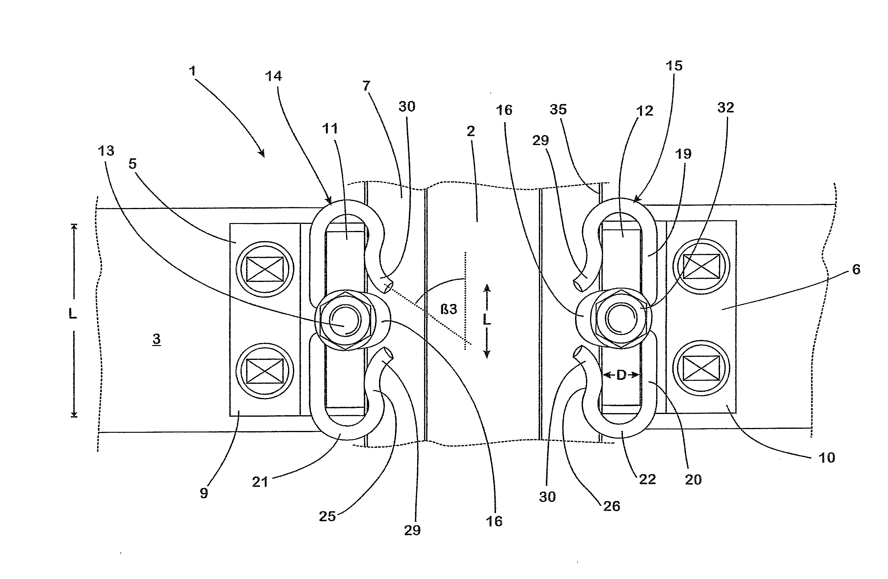
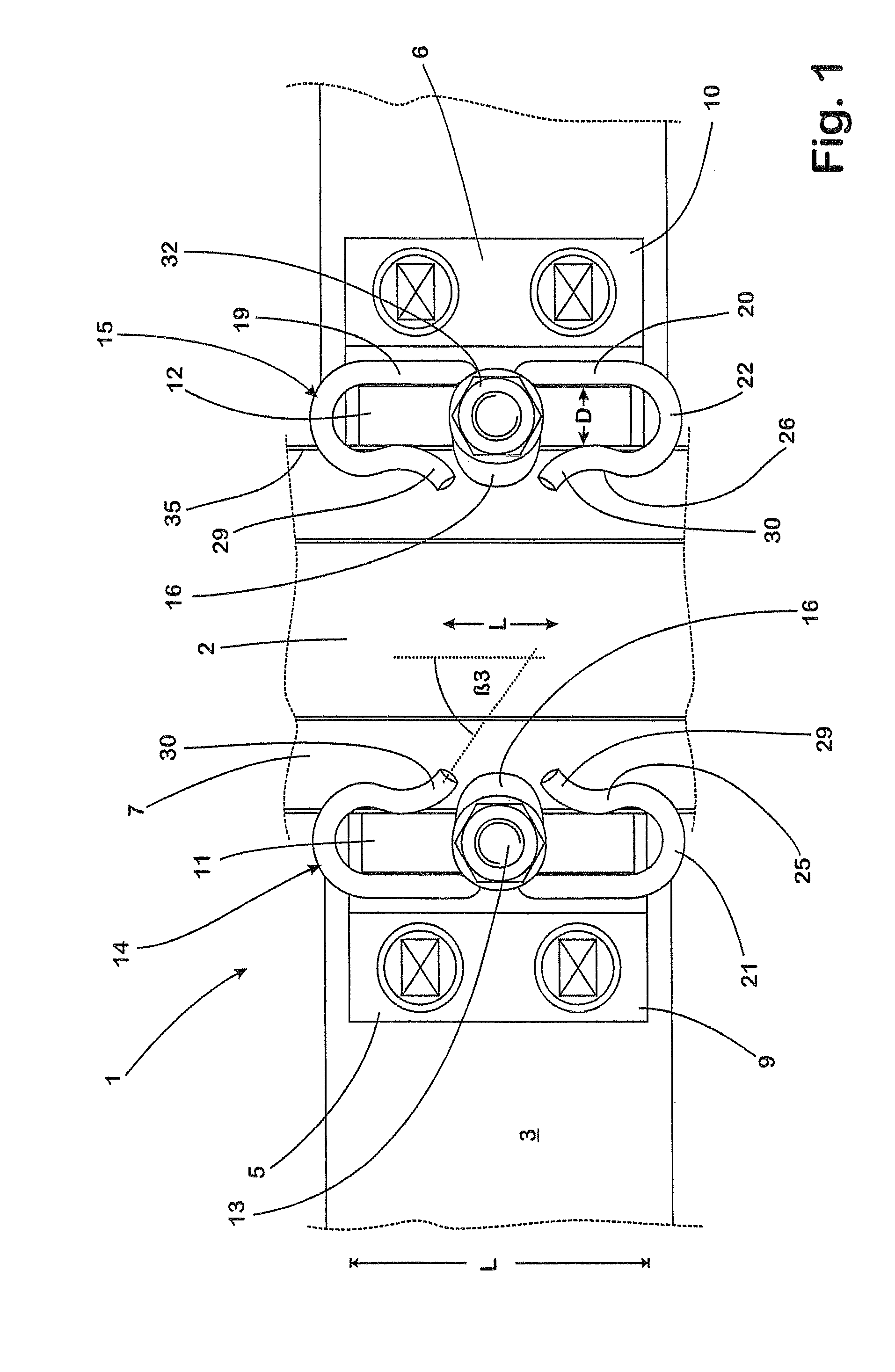
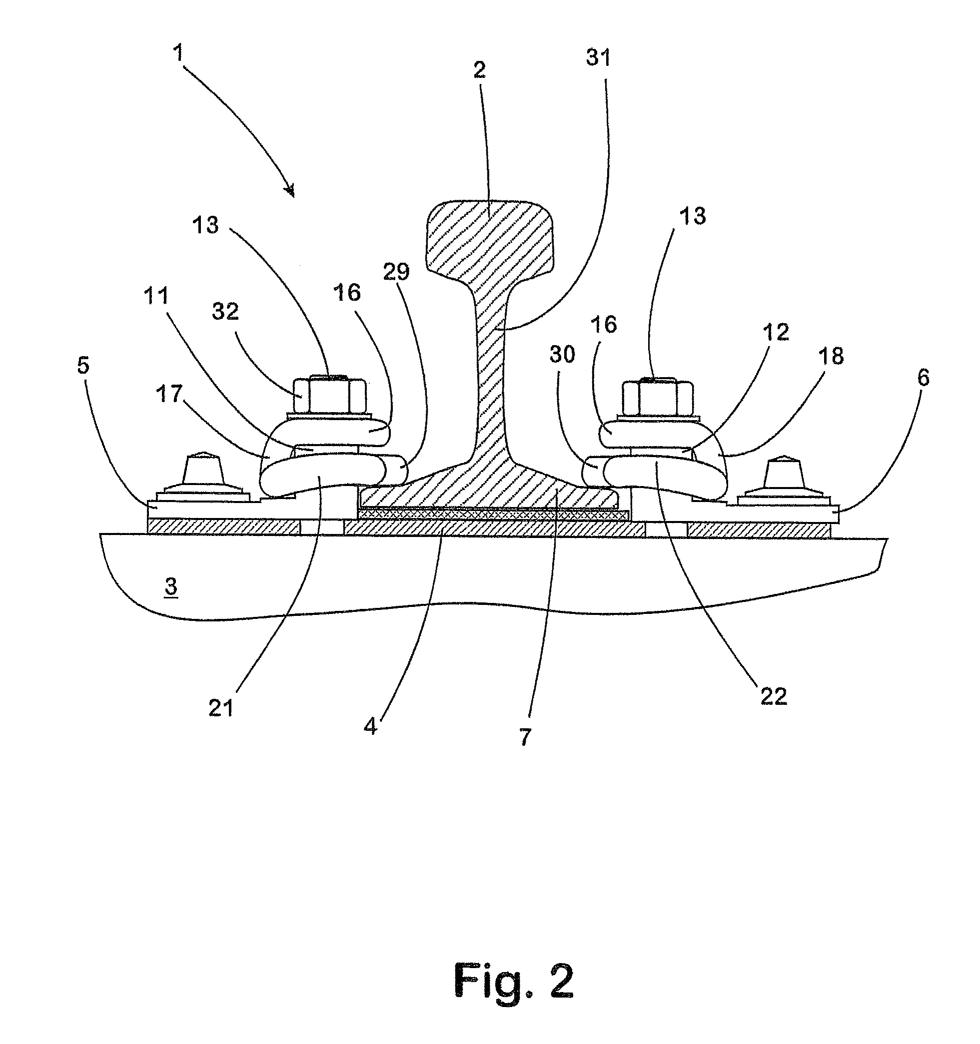
[0032]The system 1 serves to fasten a rail 2 which is part of a track body (not illustrated in greater detail). The rail fastening system 1 has two respective identically shaped carrying plates 5, 6 which are arranged above a base plate 4 on a sleeper, a plate or another substrate 3 suitable for carrying the track body and are referred to by specialists also as “rib plates”. The carrying plates 5, 6 are arranged resting in opposition against the foot 7 of the rail 2 and screwed to the substrate 3 in a manner known per se by means of screws. In order to support the rail 2 on the base plate 4 with defined flexibility in the vertical direction, a resilient layer is provided between the rail foot 7 and the base plate 4 in a manner known per se.

[0033]The carrying plates 5, 6 have, viewed from above, a respective rectangular basic shape having a length LT measured parallel to the longitudinal axis L of the rail 2. In the region adjoining the narrow side 8 which is remote from the rail 2, ...


PUM


Abstract

A system for fastening a rail having a rail foot, a web positioned thereon, and a rail head, includes a tensioning clamp with a carrying plate. The carrying plate has a central portion for bracing the tensioning clamp on the carrying plate, at least one torsion portion branching off from the central portion in the lateral direction and a holding arm connected to the torsion portion via a curved transition portion. The holding arm extends, starting from the transition portion, counter to the torsion portion and exerts via the free end of its end portion a resilient holding-down force on the rail foot of the rail to be fastened. The length of the torsion portion and the course of the transition portion is adapted to each other in such a way that at least the transition portion is guided without supports laterally past a region of the carrying plate that is associated with the central portion of the tensioning clamp. The end portion of the holding arm is angled away from the torsion portion in such a way that it points in the direction of the web of the rail to be fastened.

Description

BACKGROUND OF THE INVENTION[0001]1. Field of the Invention[0002]The invention relates to a system for fastening a rail which has a rail foot, a web positioned thereon and a rail head. The system according to the invention comprises in this case a carrying plate and a tensioning clamp held on the carrying plate. This tensioning clamp has a central portion for bracing the tensioning clamp on the carrying plate, at least one torsion portion branching off from the central portion in the lateral direction and a holding arm which is connected to the torsion portion via a curved transition portion, extends, starting from the transition portion, counter to the torsion portion and exerts via the free end of its end portion a resilient holding-down force on the rail foot of the rail to be fastened. In this case, the length of the torsion portion and the course of the transition portion are adapted to each other in such a way that at least the transition portion is guided without supports late...

Claims


Application Information

Patent Timeline
Patent Type & Authority Patents(United States)
IPC IPC(8): E01B9/62
CPCE01B9/48
Inventor BOSTERLING, WINFRIED
Owner VOSSLOH WERKE GMBH
Features
  • R&D
  • Intellectual Property
  • Life Sciences
  • Materials
  • Tech Scout
  • Unparalleled Data Quality
  • Higher Quality Content
  • 60% Fewer Hallucinations
Learn More