Composite panel insert ring and method of using the same

a composite structure and insert ring technology, applied in the field of composite structures, can solve the problems of compromising the strength or storage capacity of the composite structure, compromising the fluid integrity “externally” as well as “internally”, and achieve the effect of mitiging the flow of fluid

Active Publication Date: 2013-04-02
NORTHROP GRUMAN CORP
View PDF17 Cites 16 Cited by
  • Summary
  • Abstract
  • Description
  • Claims
  • Application Information

AI Technical Summary

Benefits of technology

[0010]There is provided a method of forming a thru-hole within a composite structure having a plurality of internal compartments. An insert ring is connected to the composite structure to create a protective layer around the periphery of a penetration formed within the composite structure. An adhesive is disposed between the composite structure and the insert ring to create a fluid-tight seal between the insert ring and the internal fluid storage compartments. In this regard, the fluid-tight seal mitigates fluid flow between the internal compartments, as well as fluid flow into the ring.

Problems solved by technology

It is understood that today's aircraft are generally complex electro-mechanical systems, which may have components formed within or extending through the composite structure.
Although forming the thru-hole in the composite structure allows for passage of the electrical or mechanical components, it may also compromise the strength or storage capacity of the composite structure.
In particular, the fluid integrity may be compromised “externally” as well as “internally.”
The “external” fluid integrity may be compromised by opening the internal compartments to the surrounding environment.
As a result, the contents stored within the internal compartments may leak into the surrounding environment.
This may lead to hazardous consequences in the event fuel or other hazardous materials are leaked from a storage compartment in an aircraft or ship structure into the surrounding environment.

Method used


Image

  • Composite panel insert ring and method of using the same
  • Composite panel insert ring and method of using the same
  • Composite panel insert ring and method of using the same

Examples


Embodiment Construction

[0022]The detailed description set forth below in connection with the appended drawings is intended as a description of certain embodiments of the present disclosure, and is not intended to represent the only forms that may be developed or utilized. The description sets forth the various functions in connection with the illustrated embodiments, but it is to be understood, however, that the same or equivalent functions may be accomplished by different embodiments that are also intended to be encompassed within the scope of the present disclosure. It is further understood that the use of relational terms such as first and second and the like are used solely to distinguish one from another entity without necessarily requiring or implying any actual such relationship or order between such entities.

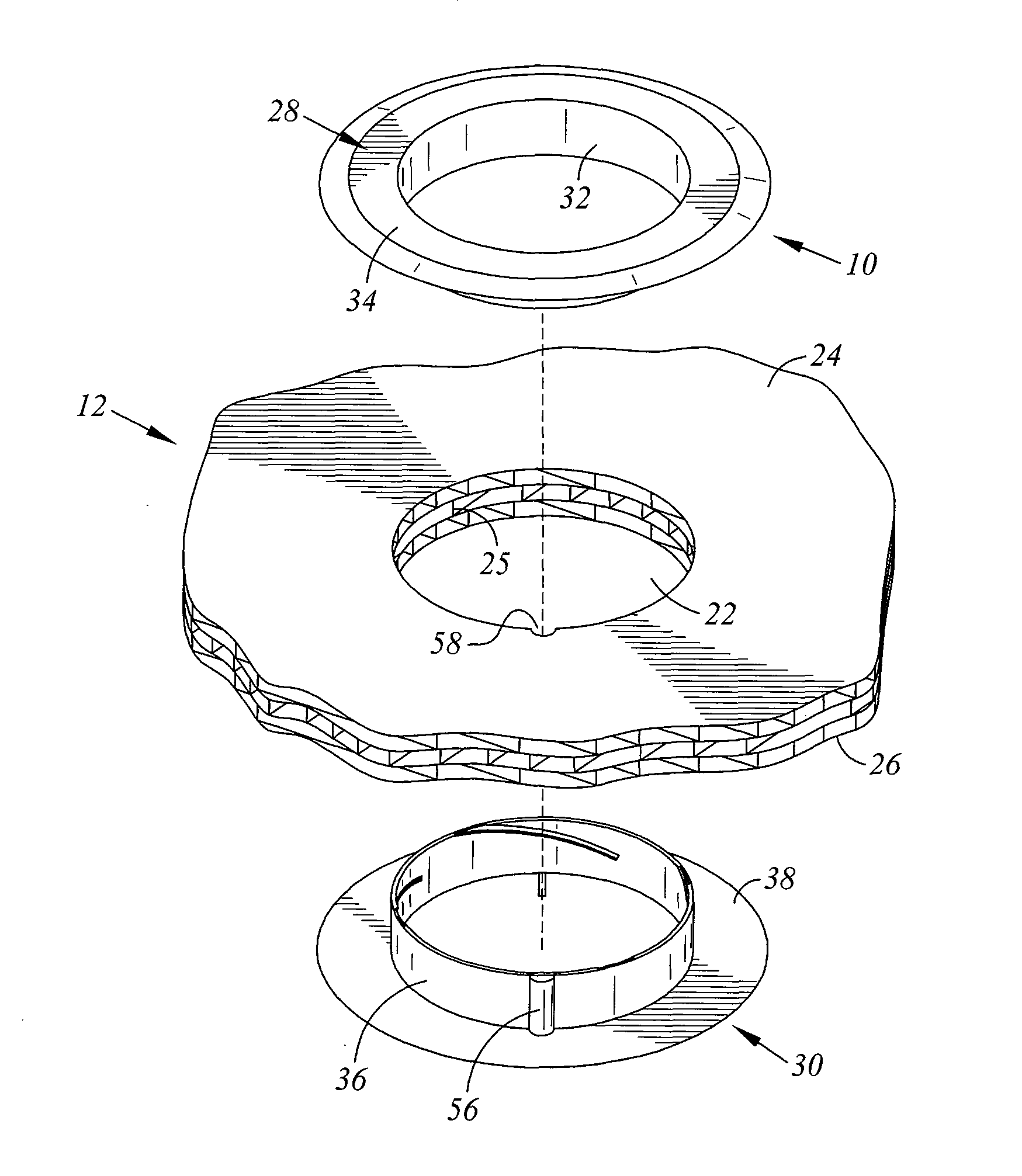
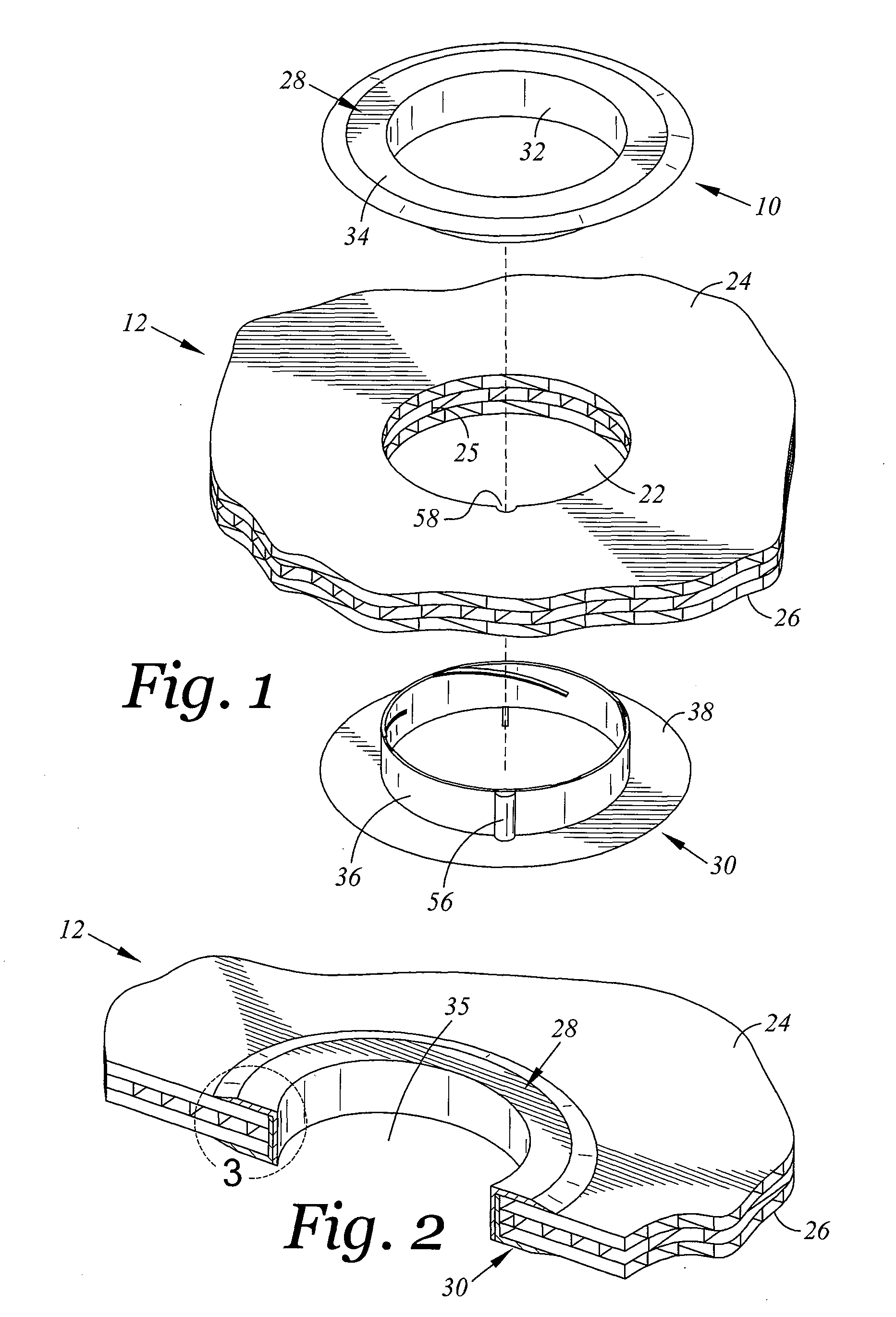
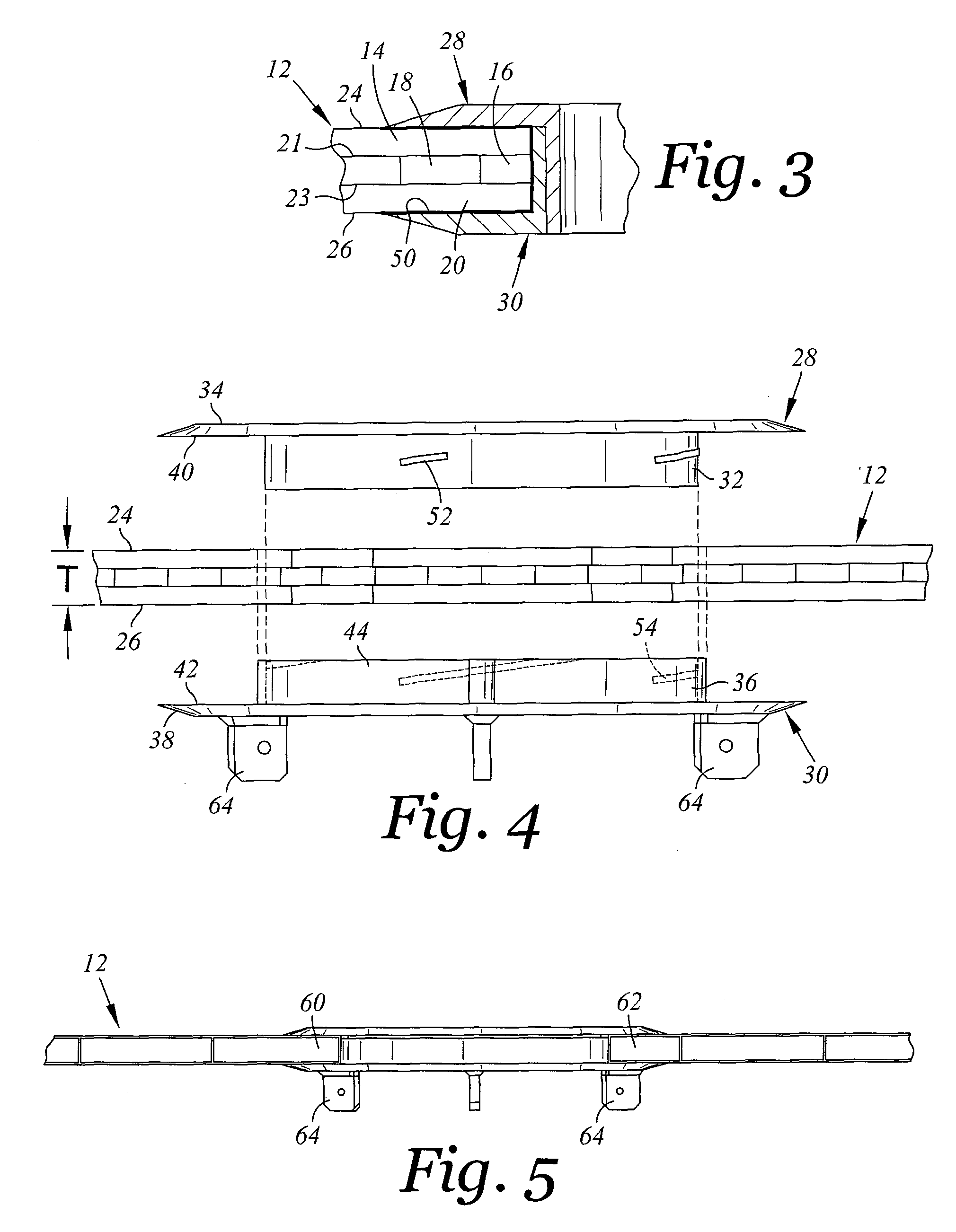
[0023]Referring now to the drawings, wherein the showings are for purposes of illustrating an embodiment of the present disclosure, and not for purposes of limiting the same, there is shown an...


PUM

PropertyMeasurementUnit
temperatureaaaaaaaaaa
internal diameteraaaaaaaaaa
adhesiveaaaaaaaaaa

Abstract

Provided is a method of forming a thru-hole through a composite structure having a plurality of internal compartments. An insert ring is connected to the composite structure to create a protective layer around the periphery of a penetration formed within the composite structure. An adhesive is disposed between the composite structure and the insert ring to create a fluid-tight seal between the insert ring and the internal compartments. In this regard, the fluid-tight seal mitigates fluid flow between the internal compartments.

Description

CROSS-REFERENCE TO RELATED APPLICATIONS[0001]Not ApplicableSTATEMENT RE: FEDERALLY SPONSORED RESEARCH / DEVELOPMENT[0002]Not ApplicableBACKGROUND[0003]The present disclosure is related generally to composite structures. More specifically, the present disclosure is directed toward an insert ring for a composite structure to provide a thru-hole within the composite structure and to fluidly seal internal compartments located therein.[0004]Composite structures have been used extensively in the aerospace and marine industries. For instance, composite panels may be used to form the wing or fuselage of an aircraft, or a portion of a ship's hull or deckhouse. The composite panels are configured to provide suitable strength and stiffness, while at the same time defining a storage boundary or capacity for storage of various contents (i.e., fuel) therein.[0005]It is understood that today's aircraft are generally complex electro-mechanical systems, which may have components formed within or exten...

Claims


Application Information

Patent Timeline
Patent Type & Authority Patents(United States)
IPC IPC(8): B29C65/00
CPCB64C1/14B32B37/14B63B3/16B63B15/00B63B19/00Y10T16/05Y10T156/1057B63B2005/242B33Y80/00
Inventor SCHUMACHER, JR., RAYMOND L.LOUDER, WILLIAM B.ARNOLD, DOUGLAS E.
Owner NORTHROP GRUMAN CORP
Why Eureka
Try Eureka