Printing system, printing apparatus and print control method therefor

a printing system and printing apparatus technology, applied in the field of printing systems, can solve the problems of inability to perform printing, large amount of time, and inability to execute jobs, so as to prevent an increase in network traffic and the effect of preventing the increase of network traffic and avoiding the unnecessary transfer of job data

Inactive Publication Date: 2013-04-02
CANON KK
View PDF5 Cites 0 Cited by
  • Summary
  • Abstract
  • Description
  • Claims
  • Application Information

AI Technical Summary

Benefits of technology

[0013]The present invention is designed to prevent an increase in network traffic and wait time for printing by eliminating an unnecessary transfer process of job data when a print job is transferred to be printed by another printing apparatus.

Problems solved by technology

Accordingly, a situation can occur in which a job is not executed or the execution of a job is delayed due to problems that have occurred in the MFP, heavy job traffic, etc.
For example, to transfer large-size job data including image data, the job data must be transferred via a network, and written into the hard disk of the apparatus to which the job data is transferred, which requires a large amount of time.
As such, various problems occur if the transfer of the job data starts at the timing at which the user has provided the instruction to transfer the job.
However, Device B is in a state in which it is unable to perform printing due to paper jam error.
In this case, the transfer of the job data from Device A to Device B is unnecessary, and the time required for the transfer not only causes a reduction in the throughput, but can also result in an increase in network traffic.
The time spent in such a standby state reduces the throughput until all of the jobs finish printing.

Method used


Image

  • Printing system, printing apparatus and print control method therefor
  • Printing system, printing apparatus and print control method therefor
  • Printing system, printing apparatus and print control method therefor

Examples


embodiment 1

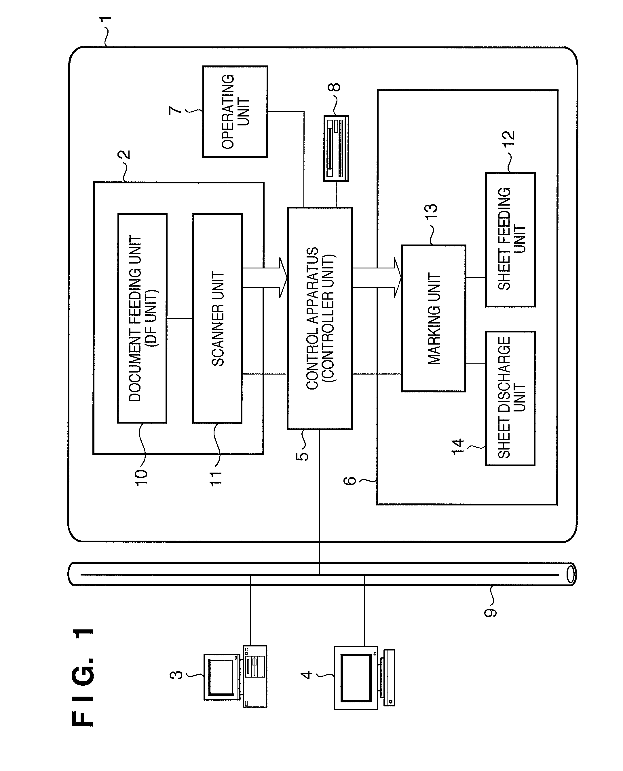
[0037]FIG. 1 is a block diagram showing a configuration of a multi-function processing apparatus (multi-function peripheral, hereinafter referred to as “MFP”) according to Embodiment 1 of the present invention.

[0038]The MFP 1 is connected to host computers (PCs 3 and 4 in the present embodiment) via a LAN (local area network) 9 such as Ethernet®. The MFP 1 includes a reader unit 2 that performs an image data readout process, and a printer unit 6 that prints the image data. An operating unit 7 is equipped with a liquid crystal panel that displays a keyboard for image data input and output operations, the image data itself, various functions, etc. A hard disk drive 8 is used to store image data and received print jobs, which shall be described later. A controller unit 5 is connected to and controls these constituent elements. The PCs 3 and 4 also function as print data sources that supply print data to the MFP 1. When making copies, the reader unit 2 functions as a print data source.

[...

embodiment 2

[0110]In Embodiment 1, in order for a transfer source device and a transfer destination device to specify each other during communication, transfer request data and job data transmission request data are used separately, whereas Embodiment 2 describes a control flow of transfer process when a transfer destination device and a transfer source device has been registered in advance in device settings. The system configuration and the configuration of the MFP and the like of Embodiment 2 are the same as those of Embodiment 1, and thus descriptions thereof are omitted here.

[0111]Embodiment 2 can be applied to a case where the user manually issues a transfer instruction to a device, but it is effective particularly in a case where a transfer instruction is executed automatically in accordance with a preset condition.

[0112]For the sake of simplicity, Embodiment 2 shall be described in the context where a transfer instruction is executed automatically.

[0113]As the preset condition, for exam...


PUM


Abstract

When an instruction to transfer a print job, which has been issued from a print data source to Device A, to Device B is made, a transfer request for the job is issued from Device A to Device B (1502). Device B then spools the transfer request in a print queue and issues a job data transmission request for the print job to Device A at a timing at which Device B can execute the transfer request (1503). In response to the transmission request, Device A transmits job data to Device B (1504), and Device B prints the job data (1505). Through this, an unnecessary transfer of job data from a device to another device can be eliminated, and thus throughput during transfer of job data is improved.

Description

BACKGROUND OF THE INVENTION[0001]1. Field of the Invention[0002]The present invention relates to a printing system in which a plurality of printing apparatuses are connected via a network, a printing apparatus, and a print control method thereof.[0003]2. Description of the Related Art[0004]Along with wide distribution of network environments, printer apparatuses and multi-function apparatuses (MFPs, or multi-function peripherals) that are capable of connecting to networks have emerged, and now shared use of multiple MFPs by multiple users has become common in office environments. In such environments, an MFP is often installed in a location that is remote from most of the users. Accordingly, a situation can occur in which a job is not executed or the execution of a job is delayed due to problems that have occurred in the MFP, heavy job traffic, etc. If such a situation occurs, the user becomes aware of the fact that a job has not been executed only after he / she goes to the location ...

Claims


Application Information

Patent Timeline
Patent Type & Authority Patents(United States)
IPC IPC(8): G06F15/00G06K1/00
CPCG06F3/1213G06F3/122G06F3/1261
Inventor ISHIKAWA, AKIRA
Owner CANON KK
Why Eureka
Try Eureka