

Image forming optical system and electronic image pickup apparatus using the same
a technology of optical system and electronic image, applied in the direction of projectors, instruments, printers, etc., can solve the problems of chromatic aberration, and affecting the image quality of the image,
- Summary
- Abstract
- Description
- Claims
- Application Information
AI Technical Summary
Benefits of technology
Problems solved by technology
Method used
Image

Examples
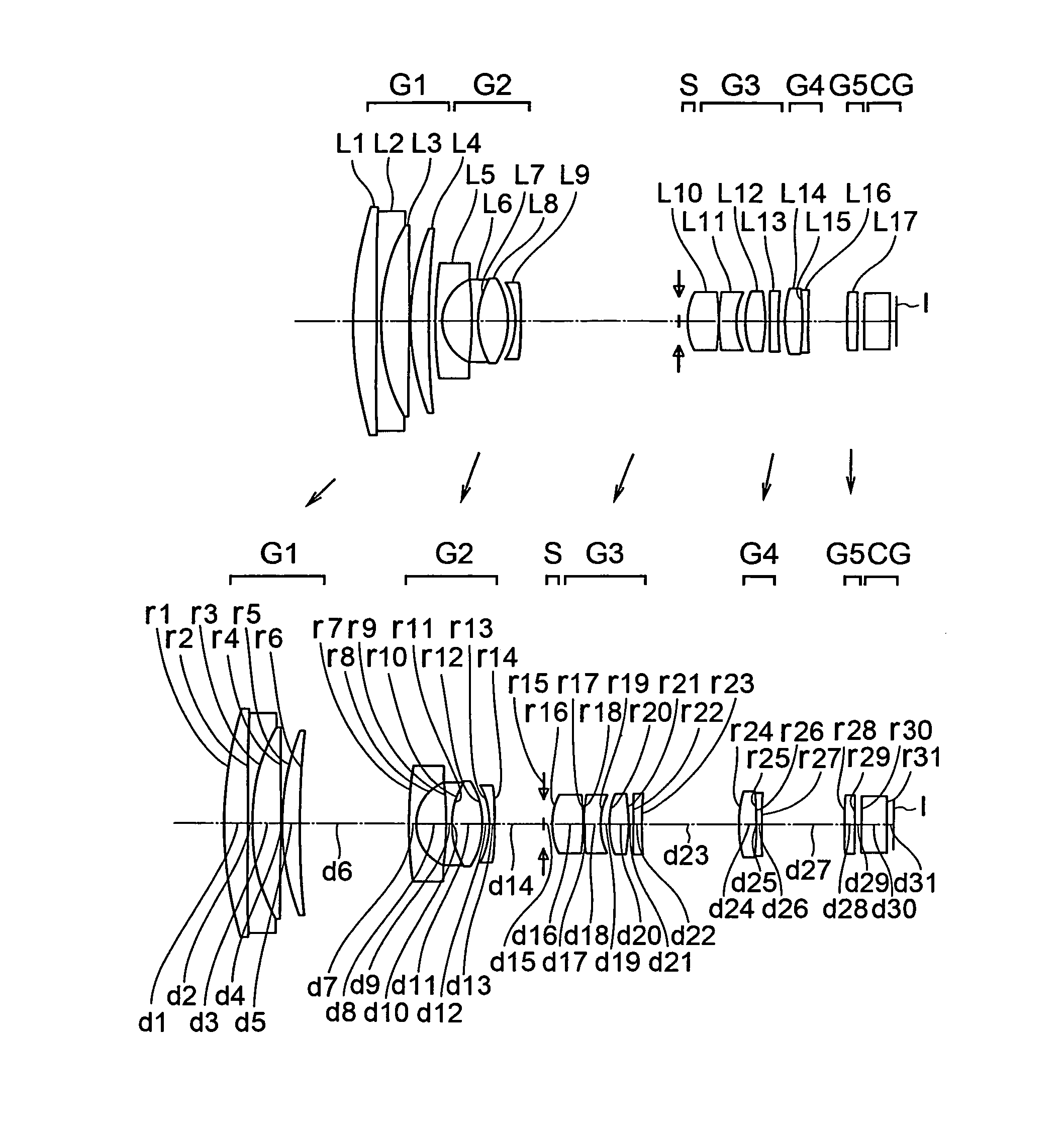
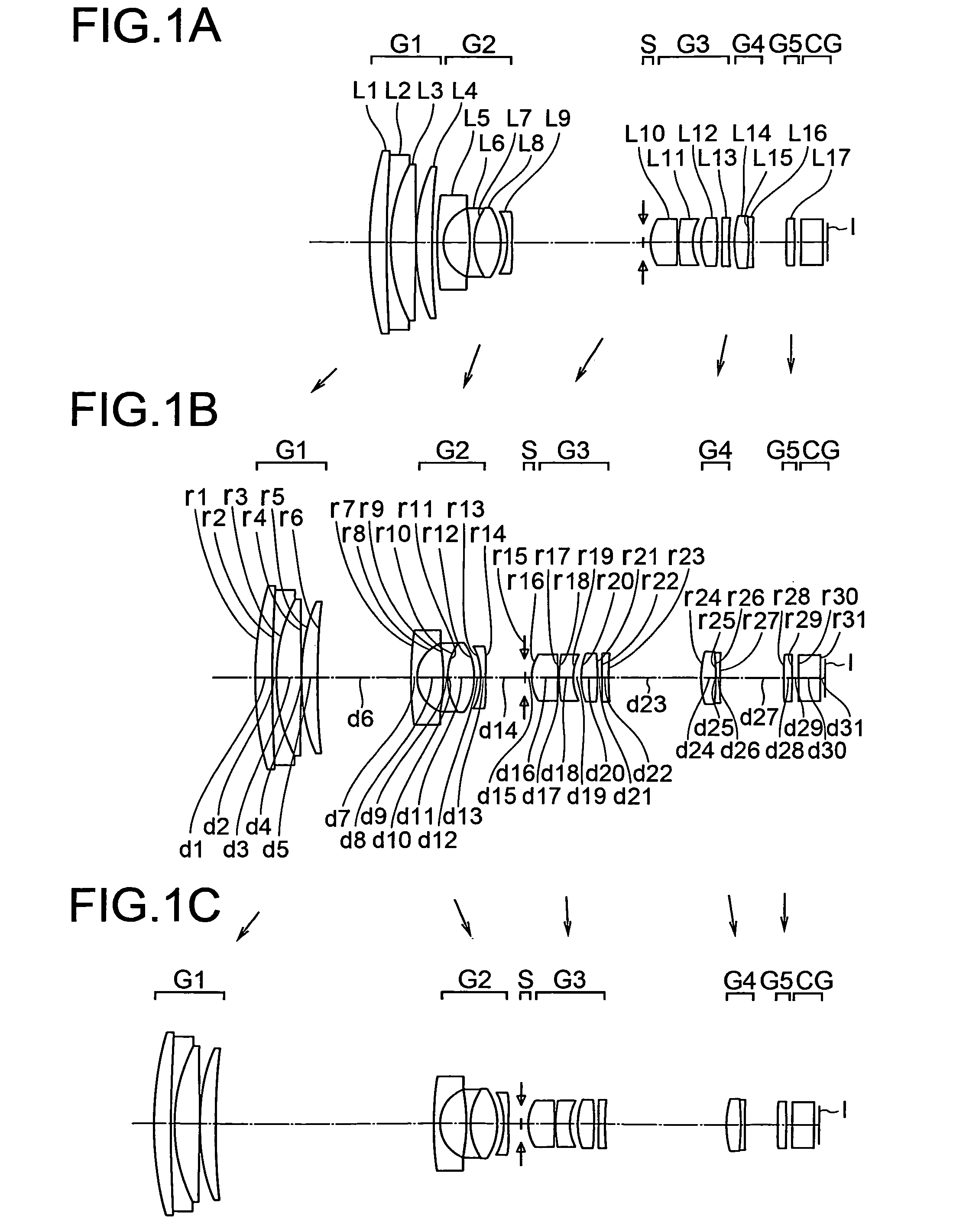
example 1
[0288]
Unit mmSurface dataeffectiveSurface no.rdndνdradiusObject plane∞∞ 170.8092.961.6338723.3817.50 2230.8070.741.6349323.9016.71 334.4534.591.4970081.5414.83 4752679.4190.1014.70 543.4342.861.7880047.3714.29 6129.755Variable14.00 763.3261.101.8830040.768.71 87.2094.796.13 9−46.2540.801.8830040.766.021012.3960.011.5140042.836.031112.3964.871.7847225.686.0312−13.4111.156.1013−13.6020.801.7725049.605.5114*−679.809Variable5.5115(stop)∞1.303.6216*10.7434.931.5891361.144.2117−78.0510.104.251828.0412.771.8466623.784.241910.6321.423.992014.2303.121.4970081.544.2721−36.9850.644.3322*58.0771.361.5307155.694.3223*34.607Variable4.312419.1302.681.4970081.544.7325−119.0900.011.5140042.834.6026−119.0900.821.8040046.574.602776.031Variable4.5528*147.3741.631.5307155.694.1429*−67.9391.094.0630∞4.001.5168064.204.0031∞0.973.84Image plane∞Aspherical surface data14th surfaceK = 0.000, A2 = 0.0000E+00, A4 = −9.19823e−05, A6 = −8.80923e−07,A8 = 4.39702e−08, A10 = −1.24247e−0916th surfaceK = 0.000, A2 = 0...
example 2
[0289]
Unit mmSurface dataeffectiveSurface no.rdndνdradiusObject plane∞∞ 166.4983.651.6338723.3817.90 21176.0990.581.6349323.9017.13 333.2074.601.4874970.2314.83 41355.9880.1014.70 538.8992.781.6968055.5314.23 6120.085Variable14.00 763.3261.101.8830040.768.71 87.2094.796.13 9−46.2540.801.8830040.766.041012.3960.011.5140042.836.061112.3964.871.7847225.686.0712−13.4111.156.1413−13.6020.801.7725049.605.5814*−679.809Variable5.5915(stop)∞1.303.7916*10.7434.931.5891361.144.3917−78.0510.104.401828.0412.771.8466623.784.381910.6321.424.102014.2303.121.4970081.544.3521−36.9850.644.4022*78.2471.361.5307155.694.3723*34.607Variable4.372419.1302.681.4970081.544.8025−119.0900.011.5140042.834.6726−119.0900.821.8040046.574.672776.031Variable4.6228*147.3741.631.5307155.694.1329*−67.9061.094.0530∞4.001.5168064.203.9931∞1.093.84Image plane∞Aspherical surface data14th surfaceK = 0.000, A2 = 0.0000E+00, A4 = −9.41129e−05, A6 = −3.64343e−07,A8 = 6.43993e−09, A10 = −6.00440e−1016th surfaceK = 0.000, A2 = 0....
example 3
[0290]
Unit mmSurface dataeffectiveSurface no.rdndνdradiusObject plane∞∞ 167.5962.711.6338723.3817.50 21210.5120.771.6349323.9017.19 333.5154.581.4874970.2314.85 4108051.9580.1014.70 538.1442.791.7291654.6814.24 6110.004Variable14.00 761.2051.101.8830040.768.89 87.2224.796.21 9−46.2540.801.8830040.766.141012.3960.011.5140042.836.181112.3964.871.7847225.686.1812−13.4111.156.2613−13.6250.801.7725049.605.6814*−663.540Variable5.7015(stop)∞1.303.7716*10.7434.931.5891361.144.3617−78.0510.104.361828.0412.771.8466623.784.351910.6321.424.062014.2303.121.4970081.544.3121−36.9850.644.3522*95.1991.361.5307155.694.3323*34.607Variable4.322419.1302.681.4970081.544.7625−119.0900.011.5140042.834.6326−119.0900.821.8040046.574.632776.031Variable4.5828*147.3741.631.5307155.694.1229*−67.9391.094.0430∞4.001.5168064.203.9831∞1.103.83Image plane∞Aspherical surface data14th surfaceK = 0.000, A2 = 0.0000E+00, A4 = −9.24299e−05, A6 = −5.56887e−07,A8 = 1.22900e−08, A10 = −6.66277e−1016th surfaceK = 0.000, A2 = ...
PUM
 Abstract
Description
Claims
Application Information