Molded lens
a mold and lens technology, applied in the field of lenses, can solve the problems of difficult to achieve satisfactory transfer of mold surface profile, easy burr, and difficult air to come out of mold, and achieve the effect of deteriorating optical performance in the effective area
- Summary
- Abstract
- Description
- Claims
- Application Information
AI Technical Summary
Benefits of technology
Problems solved by technology
Method used
Image
Examples
example 1
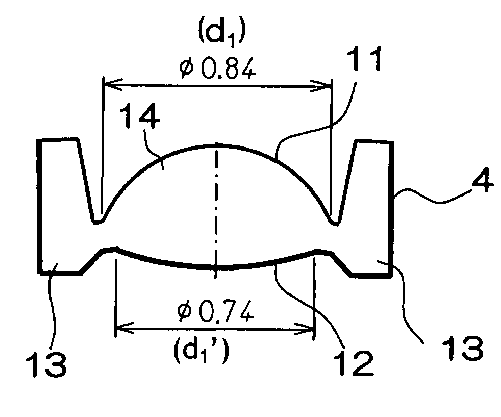
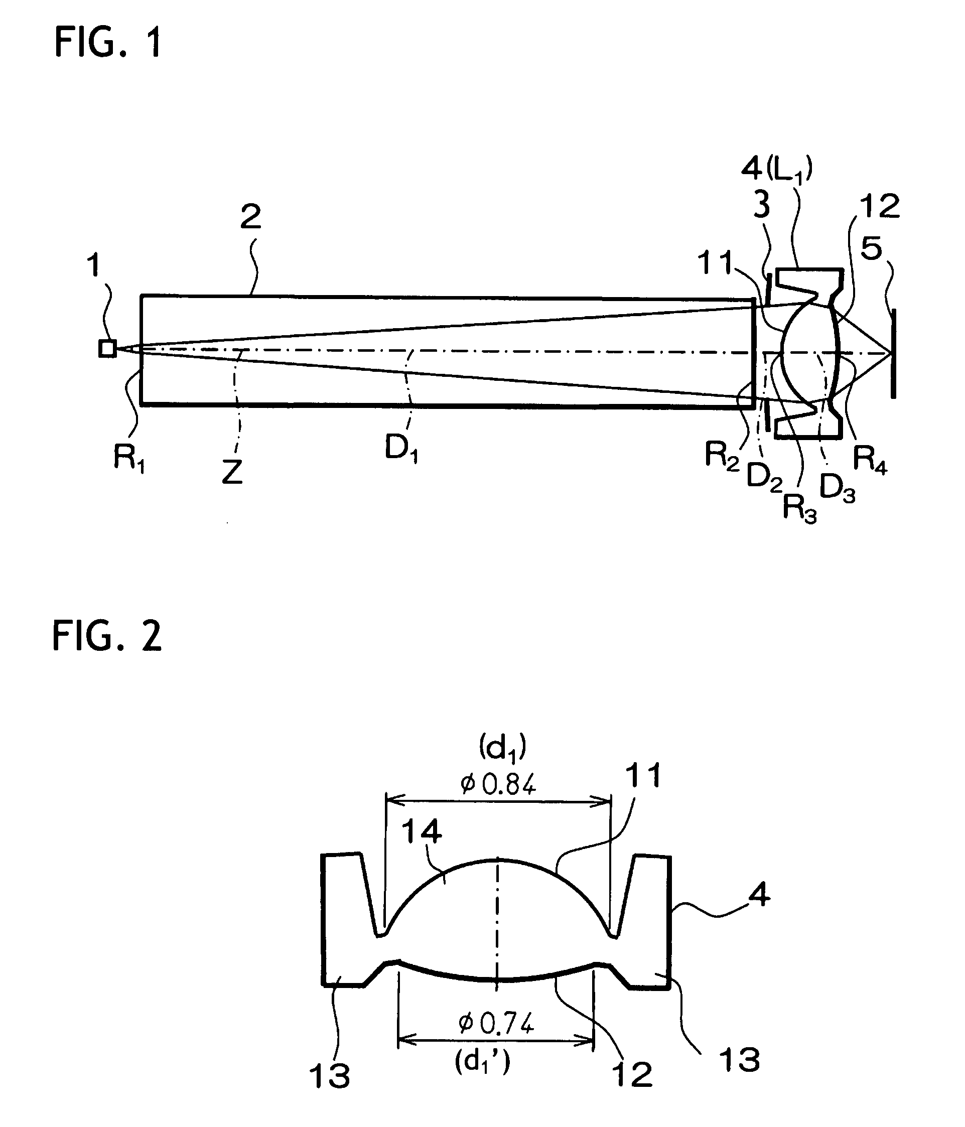
[0058]The molded lens according to Example 1 of the invention was formed by molding plastic material using the injection molding mold. As shown in FIG. 1, this molded lens was formed of a single lens L1, and also a surface of the lens L1 on the light source side (third surface) and a surface of the lens L1 on the image surface side (fourth surface) were formed into an aspheric shape.
[0059]Here, these aspheric surfaces are given by following aspheric formula.
Z=C·Y21+1-K·C2·Y2+A2Y4+A3Y6+A4Y8+A5Y10(4)
Where
[0060]Z: a length of perpendicular from a point on an aspheric surface at a height Y from an optical axis to a tangent plane (a plane perpendicular to the optical axis) of an aspheric vertex[0061]C: reciprocal of a radius of curvature R of the aspheric surface near the optical axis[0062]Y: height from the optical axis[0063]K: eccentricity[0064]A2, A3, A4, A5: fourth, sixth, eighth, and tenth-order aspheric coefficients
[0065]Also, respective numerical values concerning the optical syst...
example 2
[0072]Like Example 1, the molded lens according to Example 2 of the invention was formed by molding the plastic material using the injection molding mold. As shown in FIG. 5, this molded lens was formed of a single lens 4, and also a surface of the lens 4 on the light source side (first surface) and a surface of the lens 4 on the image surface side (second surface) were formed into the aspheric shape. Here, reference symbols in FIG. 5 correspond to those of Example 1 shown in FIG. 2 (this is also true of Example 3 in FIG. 8).
[0073]Here, these aspheric surfaces are given by above aspheric formula.
[0074]Also, respective numerical values concerning the molded lens 4 according to this Example 2 are shown in the following table 3.
[0075]In the middle stage of the table 3, a radius of curvature R (mm) of each optical surface, a surface separation D (mm) on the optical axis Z, and a refractive index N in the used wavelength of each lens are given. Here, the numbers in this stage denote the ...
example 3
[0080]FIG. 7 is a view showing the configuration of an optical system of an optical recording device using a molded lens according to Example 3 of the invention. FIG. 8 is an enlarged view showing the molded lens according to Example 3.
[0081]The device shown in FIG. 7 is constructed substantially similarly to the configuration of the optical system of the optical recording device using the molded lens according to the above Example 1 shown in FIG. 1. Therefore, the same reference symbols are assigned to the respective portions corresponding to those in FIG. 1, and their detailed explanation will be omitted herein.
[0082]The molded lens according to Example 3 of the invention was formed by molding a glass material using the compression molding mold. As shown in FIG. 7, this molded lens was formed of a single lens L1, and also a surface of the lens L1 on the light source side (third surface) and a surface of the lens L1 on the image surface side (fourth surface) were formed into an asp...
PUM
 Abstract
Description
Claims
Application Information
 - R&D
- Intellectual Property
- Life Sciences
- Materials
- Tech Scout
- Unparalleled Data Quality
- Higher Quality Content
- 60% Fewer Hallucinations
Browse by: Latest US Patents, China's latest patents, Technical Efficacy Thesaurus, Application Domain, Technology Topic, Popular Technical Reports.
© 2025 PatSnap. All rights reserved.Legal|Privacy policy|Modern Slavery Act Transparency Statement|Sitemap|About US| Contact US: help@patsnap.com


