Optical Component Having an Improved Transient Thermal Behavior and Method for Improving the Transient Thermal Behavior of an Optical Component

a technology of optical components and thermal behavior, applied in the direction of instruments, lighting and heating apparatus, photomechanical apparatus, etc., can solve the problems of poor heat conduction ability, poor heat carrying off, and high temperature, and achieve the effect of avoiding or at least reducing deteriorations and being less expensiv

Inactive Publication Date: 2009-01-22
CARL ZEISS SMT GMBH
View PDF10 Cites 0 Cited by
  • Summary
  • Abstract
  • Description
  • Claims
  • Application Information

AI Technical Summary

Benefits of technology

[0013]It is an object of the present invention to provide another cooling concept for an optical component which is less expensive on the one hand, and on the other hand is nevertheless effective in avoiding or at least reducing deteriorations due to heating effects of the optical component and, thus, of the optical system, in which the optical component is used.
[0014]It is another object of the present invention to provide an optical component which, on the basis of an optimization of this thermal behavior, contributes to allowing deterioration of the optical performance of the optical element during operation at least to be reduced.
[0015]A further object of the present invention is to provide an optical component which is improved with regard to its transient thermal behavior, so that transient effects that are caused by the heating of the optical component and disturb the optical performance of the optical element, primarily defocusing and / or illumination in the far field, can at least be reduced.

Problems solved by technology

In most cases, this heat is poorly carried off, because the fixing element 6 to the holder 7 and also the substrate material 4 have a poor heat conduction ability.
If no heat carrying off is provided by heat conduction into a cooling medium, the temperatures can become pretty high and rapidly exceed an operating temperature which is in some cases required.
This cooling apparatus is expensive, because it requires a considerable number of additional parts, thus also increasing the space requirements of the optical component.
On the one hand, the optical component becomes too hot, as a result of which the substrate material and the optical layers can be destroyed.
On the other hand, the optical component can be deformed so severely that the optical performance of the system does not conform to the required specification.
A one-off or static correction of the resultant error in the optical system, for example with the aid of other optical components, would therefore be inadequate.

Method used


Image

  • Optical Component Having an Improved Transient Thermal Behavior and Method for Improving the Transient Thermal Behavior of an Optical Component
  • Optical Component Having an Improved Transient Thermal Behavior and Method for Improving the Transient Thermal Behavior of an Optical Component
  • Optical Component Having an Improved Transient Thermal Behavior and Method for Improving the Transient Thermal Behavior of an Optical Component

Examples


Embodiment Construction

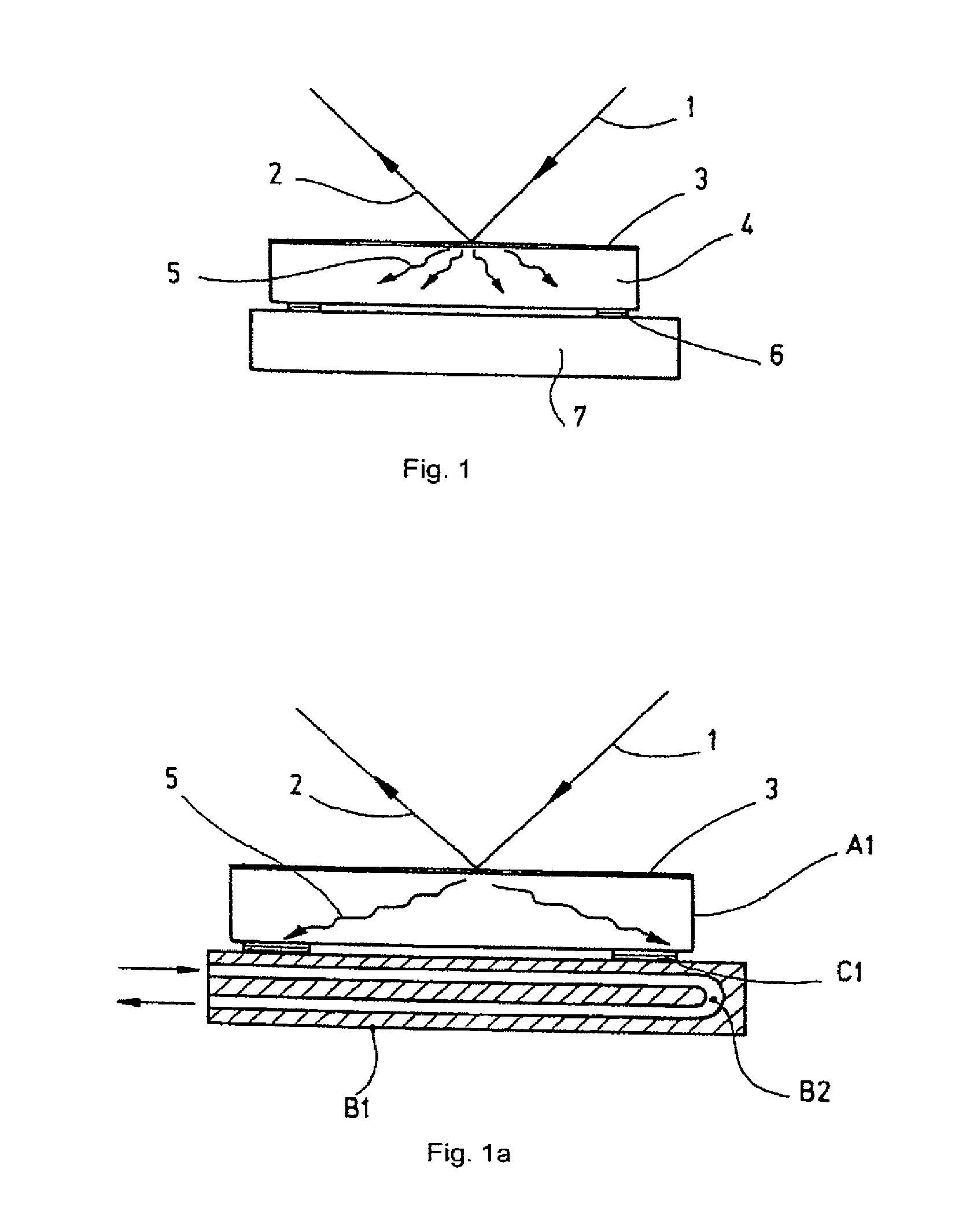
[0070]FIG. 1a generally shows an optical component which is comparable with the optical component shown in FIG. 1. Reference numerals used in FIG. 1a which are identical with those reference numerals in FIG. 1 denote same features as in FIG. 1, and they are not described here again.

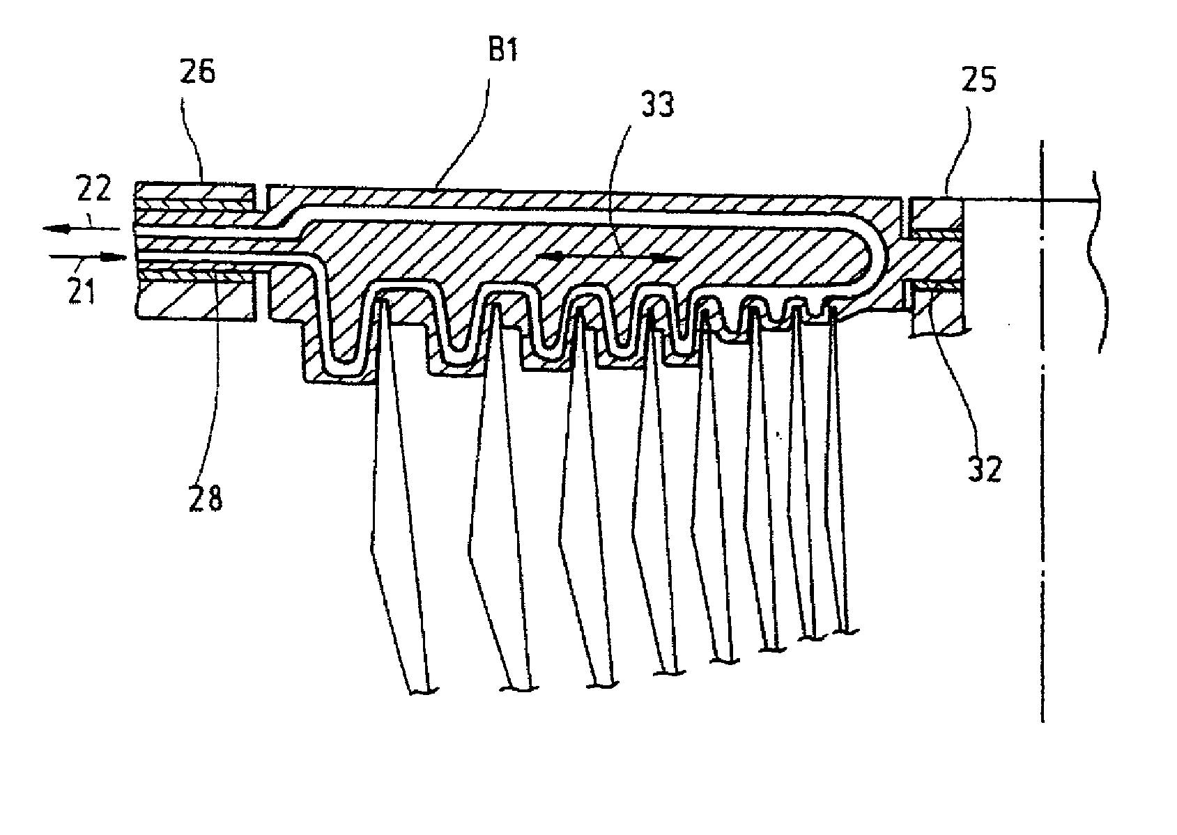
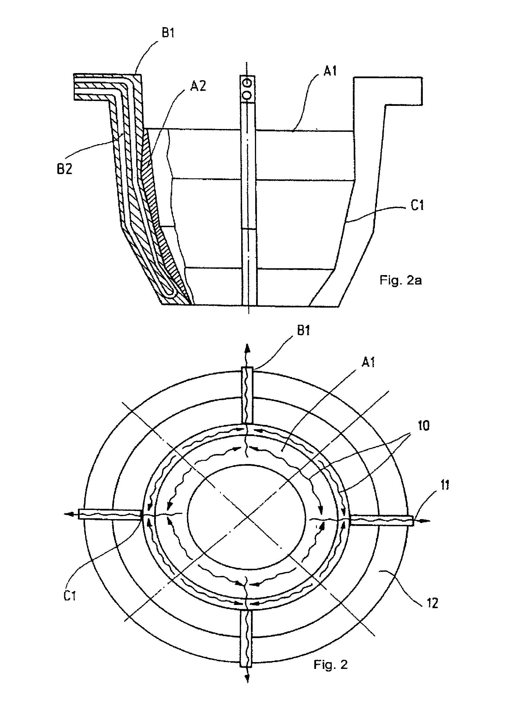
[0071]FIG. 1a generally shows the heat conduction from an optical element A1 of the optical component into the holder or holding element B1 according to the present invention. The optical element of the optical component comprises a substrate A1 made of a highly heat-conductive material (for example copper, aluminum, SiC) and having a large cross-section. The holder B1 comprises one or several cooling channels B2 which is or which are flown through by a cooling medium. The optical element A1 is connected to the holding element B1 by means of a highly heat-conductive connecting element or connecting means C1 which has one or several of the following characteristics: a large contact area for contacting the ...


PUM


Abstract

An optical component comprises at least one optically effective optical element which heats up when irradiated with light, and at least one holding element for the at least one optical element for holding the at least one optical element in a carrier structure, wherein the at least one optical element is connected to the at least one holding element in heat conducting fashion, and wherein the at least one holding element is at least partially provided with an active cooling system for carrying off heat from the at least one optical element. Additionally or alternatively, a temperature control device is provided which controls the temperature of at least a part of the mount of the optical element.

Description

CROSS-REFERENCE TO RELATED APPLICATIONS[0001]The present application is a continuation of U.S. pending application Ser. No. 11 / 245,288 filed Oct. 6, 2005, which is a continuation-in-part of pending International Patent Application PCT / EP2005 / 004861 filed on May 4, 2005, which designates the United States and which claims priority of U.S. Provisional Patent Application No. 60 / 568,547 filed on May 6, 2004. Further, the U.S. patent application Ser. No. 11 / 245,288 also claims the benefit under 35 U.S.C. §119(e) of the U.S. Provisional Patent Application No. 60 / 616,464 filed on Oct. 6, 2004.BACKGROUND OF THE INVENTION[0002]The invention generally relates to improvements of the thermal behavior of an optical component. More specifically, the invention relates to improvements of the thermal behavior of a collector for use in EUV-lithography.[0003]Although the present invention will be particularly described with respect to a collector for use in EUV-lithography, the present invention is no...

Claims


Application Information

Patent Timeline
Patent Type & Authority Applications(United States)
IPC IPC(8): B60Q1/06
CPCB82Y10/00G03F7/70166G03F7/70175G21K2201/067G21K1/06G21K2201/065G03F7/70858
Inventor EGLE, WILHELMHAFNER, WOLFGANGANDERL, WILLIBINGEL, ULRICHMUENZ, HOLGERNEIDHARDT, THOMAS
Owner CARL ZEISS SMT GMBH
Why Eureka
Try Eureka