Method and device for generating a self-referenced optical frequency comb

a self-referenced optical frequency and comb technology, applied in the direction of laser optical devices, laser details, instruments, etc., can solve the problems of the inability to accurately determine the offset frequency of the carrier envelope, and the inability to achieve the offset frequency. to achieve the effect of facilitating the operation of the device and the design

Active Publication Date: 2013-04-09
HIGH Q LASER
View PDF6 Cites 14 Cited by
  • Summary
  • Abstract
  • Description
  • Claims
  • Application Information

AI Technical Summary

Benefits of technology

[0015]For compensating the carrier envelope offset frequency, the device and the method proposed here do not require any reference frequency that is not contained in the original uncompensated train of short temporally equidistant laser pulses. The method is therefore referred to as self-referencing. A compensated train of short laser pulses generated with this method thus represents a self-referenced frequency comb. In analogy to this, a device adapted to perform the method is referred to as a device for generating a self-referenced frequency comb.
[0016]The advantage that no controlling interventions in the laser oscillator are necessary facilitates the operation of the device and the design of the laser. The device may be used with any mode-coupled laser.
[0017]For determining the CEO signal it is preferably provided to conduct part of the received uncompensated train of short laser pulses into an interferometer. Such an interferometer is preferably designed as an f-to-2f interferometer. The carrier envelope offset frequency determining unit thus comprises preferably an f-to-2f interferometer and a photosensitive detector receiving a beat signal from which the CEO signal is derived. Basically, any method and any device may be used to determine the CEO signal. Some examples are described in H. R. Telle et al., Appl. Phys. B 69, 327 et seq. (1999).
[0018]In a particularly preferred manner, the CEO signal is derived from the beat signal by means of frequency filtering. To this end, a high frequency filter is preferably provided which filters the beat signal. In a particularly preferred manner, the high frequency filter is designed as a band pass filter. The high frequency filter is coarsely adjusted to the expected carrier envelope offset frequency.
[0019]In order to generate the control signal, the CEO signal is amplified in one embodiment so as to directly drive the acousto-optical frequency shifter therewith.

Problems solved by technology

Since the magnitude of the carrier envelope offset frequency fCEO is severely dependent on environmental factors, e.g. the temperature and the air pressure, but also the pumping performance of the laser medium, etc. so as to list just a few, but not all factors, the carrier envelope offset frequency is moreover not stable with respect to time.
The effort with respect to the apparatus is correspondingly high.
The systems are, however, limited due to the control electronics.
Since a free oscillation build-up has to be avoided, the regular amplification is typically limited.
This in turn results in that very quick interference components of the ΔφCEO signal (so-called “glitches”) can be compensated insufficiently only.

Method used


Image

  • Method and device for generating a self-referenced optical frequency comb
  • Method and device for generating a self-referenced optical frequency comb
  • Method and device for generating a self-referenced optical frequency comb

Examples


Embodiment Construction

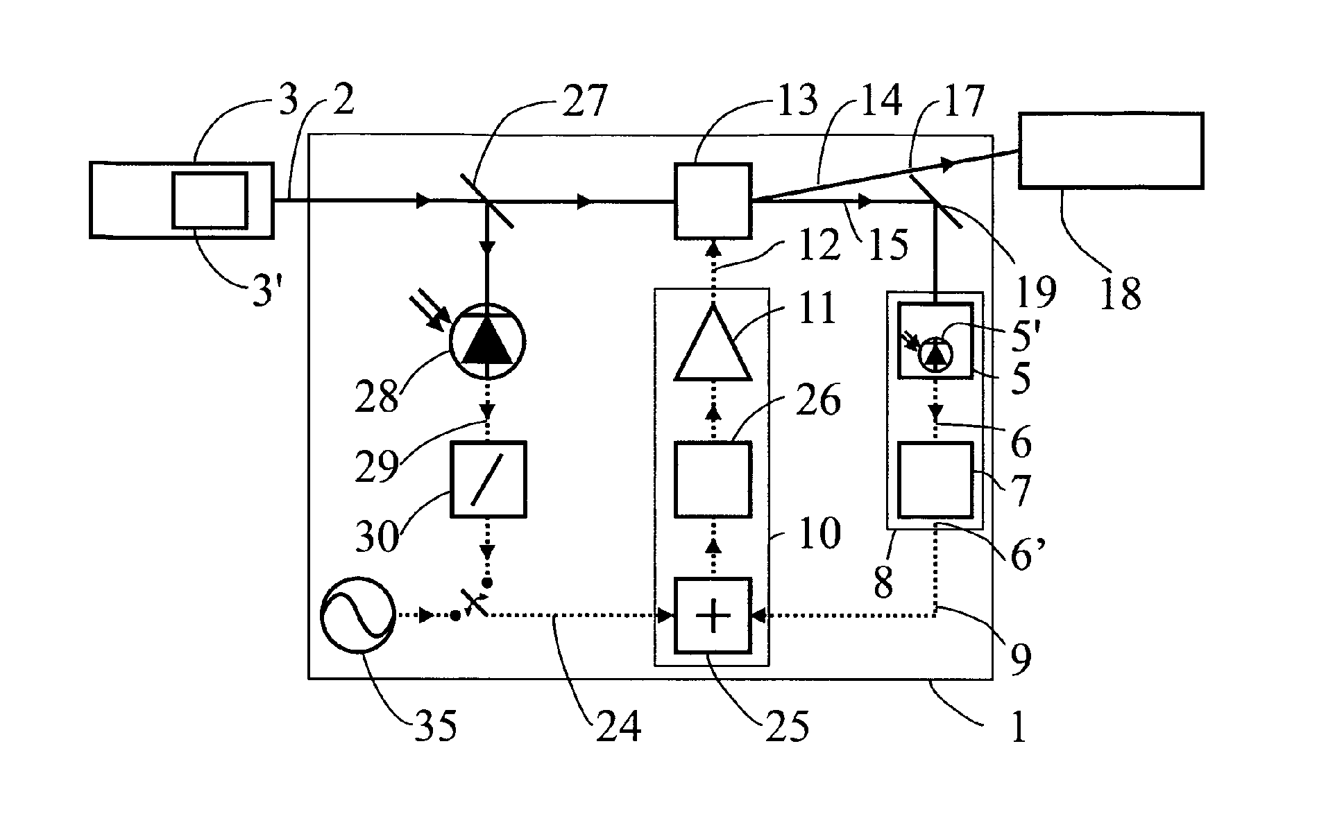
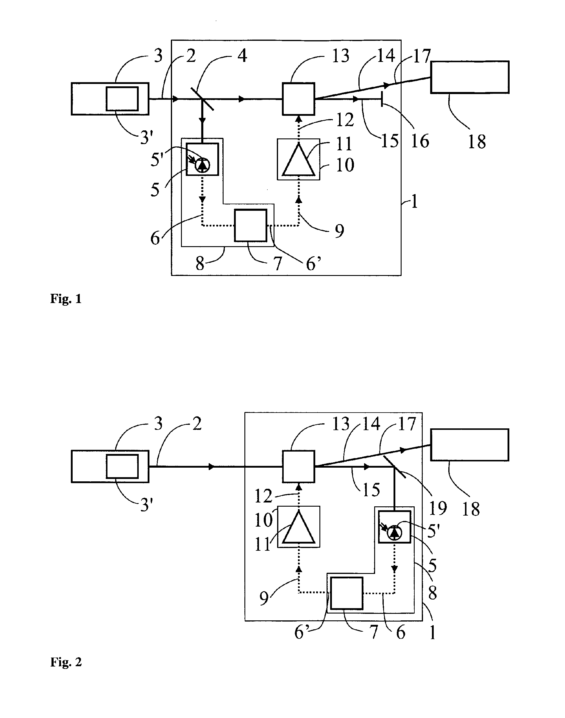
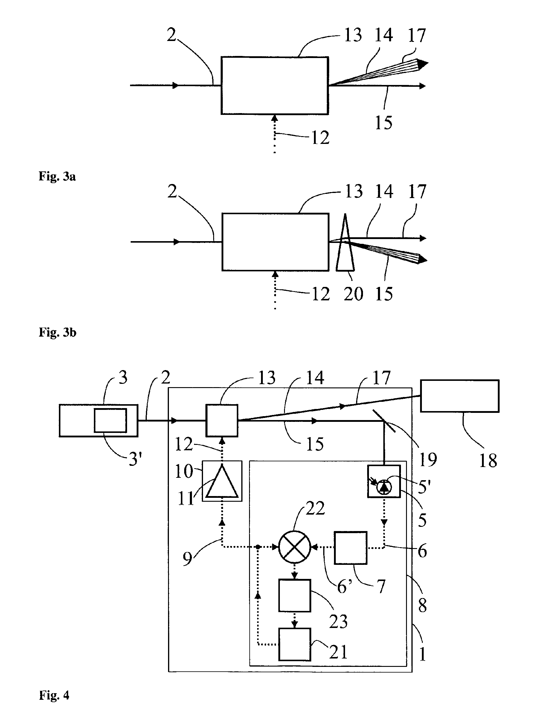
[0037]FIG. 1 schematically illustrates a device for generating a self-referenced frequency comb, or for generating a compensated train 17 of temporally equidistant short laser pulses, respectively, in which the individual lines of the frequency comb comprise a stabilized carrier envelope offset frequency. Such a device will be referred to as a device for generating a self-referenced frequency comb in the following. The device 1 is adapted to receive an uncompensated train 2 of temporally equidistant short laser pulses of a mode-coupled laser 3. The mode-coupled laser may, for instance, be a titanium:sapphire laser or an erbium fiber laser. The uncompensated train 2 of short laser pulses constitutes, when viewed in the frequency space, a frequency comb of equidistant individual lines that are also referred to as modes. The individual lines of the frequency comb have a frequency distance Δf corresponding to the inverse of the circulation period of one of the short pulses in the resona...


PUM


Abstract

The present disclosure relates to a method and to a device (1) by which a train (2, 2) of short laser pulses of a mode-coupled laser (3) is compensated with respect to the carrier envelope offset frequency of the individual lines contained in the associated frequency comb. The aim of the disclosure is to determine the carrier envelope offset frequency and to utilize said frequency to operate an acousto-optical frequency shifter (13). In said shifter, the uncompensated train of temporally equidistantly short laser pulses is diffracted in a first order such that the individual lines of the frequency comb are shifted by the carrier envelope offset frequency. The resulting compensated train of short laser pulses has a frequency comb, the individual lines of which are integral multiples of the repetition frequency of the individual light pulses in the train of short laser pulses.

Description

CROSS REFERENCE TO RELATED APPLICATIONS[0001]The present application is a 35 U.S.C. §371 National Phase conversion of PCT / AT2009 / 000469, filed Dec. 2, 2009, which claims benefit of German Application No. 10 2008 059 902.6, filed Dec. 2, 2008, the disclosure of which is incorporated herein by reference. The PCT International Application was published in the German language.FIELD OF THE INVENTION[0002]The invention relates to a method for generating a compensated train of temporally equidistant short laser pulses, the frequency comb of which comprises individual lines whose carrier envelope offset frequency is stabilized at a predetermined value, as well as to a device for generating a train of such short laser pulses. “Stabilizing” here means the setting of a magnitude to a constant value. The stabilizing to a predetermined value thus constitutes the setting of a magnitude such that this magnitude has the predetermined value constant over time.BACKGROUND OF THE INVENTION[0003]A train...

Claims


Application Information

Patent Timeline
Patent Type & Authority Patents(United States)
IPC IPC(8): H01S3/10
CPCG02F1/33H01S3/005G02F2203/56H01S3/10053
Inventor GREBING, CHRISTIANKOKE, SEBASTIANSTEINMEYER, GUNTER
Owner HIGH Q LASER
Why Eureka
Try Eureka