Image coding apparatus and image coding method

a technology of image coding and image coding, applied in the field of image coding technique, can solve the problems of large calculation volume, low correlation calculation precision, and huge calculation volume, and achieve the effect of suppressing the calculation volume and high precision

Inactive Publication Date: 2013-04-09
CANON KK
View PDF13 Cites 1 Cited by
  • Summary
  • Abstract
  • Description
  • Claims
  • Application Information

AI Technical Summary

Benefits of technology

[0010]The present invention has been made in consideration of the conventional problems. According to the present invention, there is provided an image coding apparatus and method, which can conduct a motion search with high precision while suppressing the calculation volume.

Problems solved by technology

However, upon enhancing the search precision, a calculation volume required for search becomes huge.
In addition, since this calculation is made for each of a plurality of blocks of a coding target frame, a huge calculation volume is required.
However, with the conventional binarized image search, although the calculation volume is reduced, since the input image is binarized, the correlation calculation precision is low, and the search precision of a motion destination of a coding target block, that is, that of a motion vector drops.
For this reason, this consequently results in a coding efficiency drop.
In case of an N-arized image search scheme, higher precision is assured than the binarized image search scheme, but that scheme also lowers gradation of the input image, thus posing the same problem.

Method used


Image

  • Image coding apparatus and image coding method
  • Image coding apparatus and image coding method
  • Image coding apparatus and image coding method

Examples


first embodiment

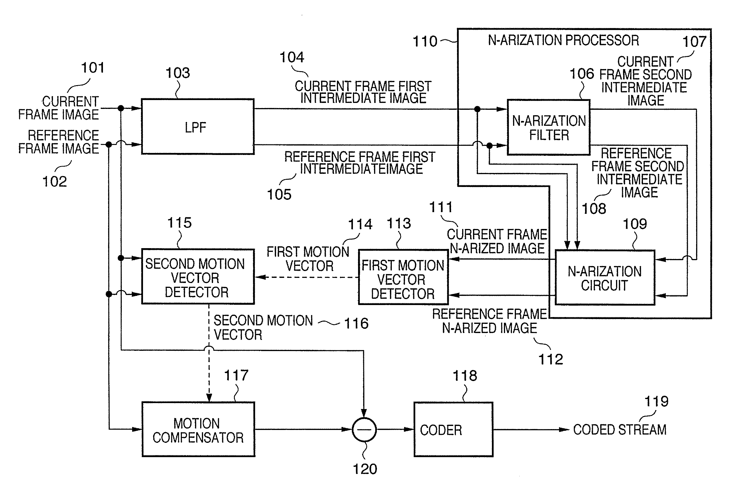
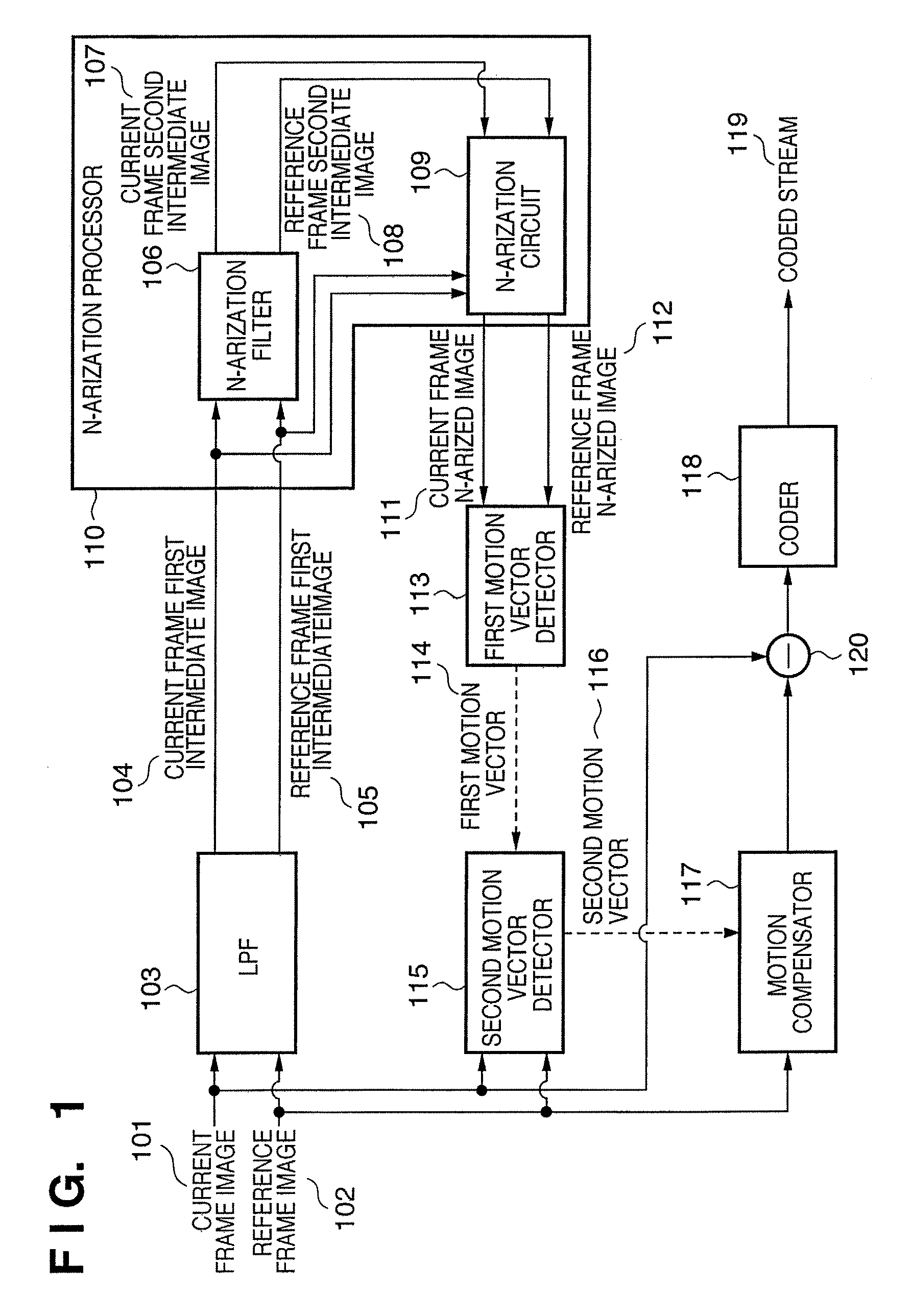
[0023]FIG. 1 is a block diagram showing an example of the arrangement of a coding apparatus according to the present invention.

[0024]Referring to FIG. 1, a coding apparatus receives a current frame image 101 as a coding target image, and a reference frame image 102 which is referred to for the purpose of a motion vector search. Both these frame images 101 and 102 are multi-valued images (M (M>2)-arized images). The reference frame image 102 is a past or future frame image of the current frame image 101 in a moving image.

[0025]An LPF 103 is a low-pass filter. The current frame image 101 undergoes filter processing by the LPF 103, and is output as a current frame first intermediate image 104. The reference frame image 102 undergoes filter processing by the LPF 103, and is output as a reference frame first intermediate image 105.

[0026]An N-arization processor 110 (M>N≧2, N is an integer) has an N-arization filter 106 and N-arization circuit 109, and N-arizes and outputs the first inter...

second embodiment

[0062]FIG. 6 is a block diagram showing an example of the arrangement of a coding apparatus according to the present invention. In FIG. 6, the same reference numerals denote the same blocks as in FIG. 1, and a repetitive description thereof will be avoided.

[0063]The coding apparatus of this embodiment is different from that of the first embodiment in that the N-arization processor 110 includes a resolution reduction circuit 601. The resolution reduction circuit 601 receives the current frame first intermediate image 104 and the reference frame first intermediate image 105, and generates low-resolution images of the input images.

[0064]For example, this embodiment generates a low-resolution image having pixels 1 / 4 those of an original image by reducing the vertical and horizontal resolutions of the original image to 1 / 2. This embodiment generates a low-resolution image having pixels 1 / 4 those of the original image by replacing 4 (=2×2) pixels of the original image by an average pixel ...


PUM


Abstract

In a coding apparatus for performing motion-compensated coding, N (M>N≧2)-arized images are converted from a coding target image and reference image as M-arized images, and a motion search is conducted using the N-arized images. During this process, the coding apparatus applies low-pass filter processing to the coding target image and the reference image before conversion of the N-arized images.

Description

BACKGROUND OF THE INVENTION[0001]1. Field of the Invention[0002]The present invention relates to an image coding technique and, more particularly, to an image coding technique using motion compensation.[0003]2. Description of the Related Art[0004]In image coding schemes specified by standards such as H.26x, MPEG, and the like, one moving image frame is divided into a plurality of blocks, and coding is done for each block.[0005]In these image coding schemes, a coding scheme (inter coding) that exploits temporal correlation of moving image frames, and a coding scheme (intra coding) that exploits spatial correlation in one frame can be used. The coding scheme that exploits temporal correlation searches for the position in a reference frame to which a coding target block moves, and encodes the difference between a motion vector that represents the amount of motion and direction, and the block at the motion destination, thus compressing the data amount. Such coding scheme that considers ...

Claims


Application Information

Patent Timeline
Patent Type & Authority Patents(United States)
IPC IPC(8): G06K9/36H04N19/51H04N19/533H04N19/50H04N19/57H04N19/80H04N19/85
CPCH04N19/56H04N19/59H04N19/80H04N19/51
Inventor OMORI, YUJI
Owner CANON KK
Why Eureka
Try Eureka