Method and apparatus for changing speed or direction of an article

a technology of speed or direction, applied in the direction of conveyor parts, instruments, transportation and packaging, etc., can solve the problems of high speed diaper lines, high acceleration and reversal forces in the free tail end of the product being folded, and the fluff contents of such a diaper could very well be destroyed, so as to reduce acceleration forces and high deceleration and reversal forces

Inactive Publication Date: 2013-04-09
CURT G JOA
View PDF610 Cites 21 Cited by
  • Summary
  • Abstract
  • Description
  • Claims
  • Application Information

AI Technical Summary

Benefits of technology

[0005]The present invention is used, for example, to controllably reverse the direction of the leading edge of a diaper panel as it is being cross folded. Typical cross folders used on high speed diaper lines may produce extremely high deceleration and reversal forces in the free tail end of the product being folded. One advantage provided by this invention is to reduce the acceleration forces felt by the product as it goes through the reversal process, by first carrying the article in a first direction by way of contact with the surface of a belt system which is moving in the first direction. At a point slightly before the expected reversal, the forward moving belt nip is opened and a reverse moving belt nip is engaged so that the product is stopped and then driven backwards by the second belt.

Problems solved by technology

Typical cross folders used on high speed diaper lines may produce extremely high deceleration and reversal forces in the free tail end of the product being folded.
The fluff contents of such a diaper could very well be destroyed by a “crack the whip” effect.

Method used


Image

  • Method and apparatus for changing speed or direction of an article
  • Method and apparatus for changing speed or direction of an article
  • Method and apparatus for changing speed or direction of an article

Examples


Embodiment Construction

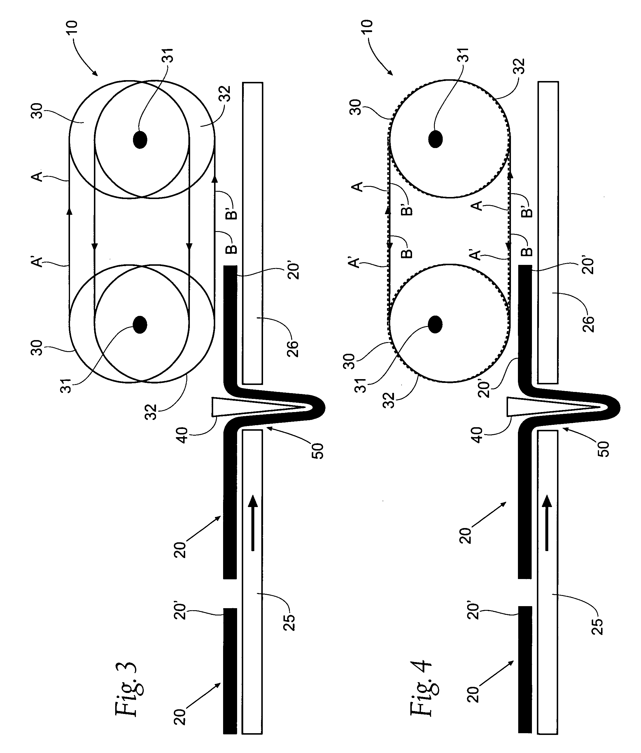
[0035]Although the disclosure hereof is detailed and exact to enable those skilled in the art to practice the invention, the physical embodiments herein disclosed merely exemplify the invention that may be embodied in other specific structure. While the preferred embodiment has been described, the details may be changed without departing from the invention. It is noted that the drawings, for clarity purposes so that the different elements can be seen, show the belts adjacent to but not contacting, the articles. This is merely for drawing clarity, it being understood that the belts move into contact with the articles when indicated by the text below, and out of contact with the articles when indicated by the text below.

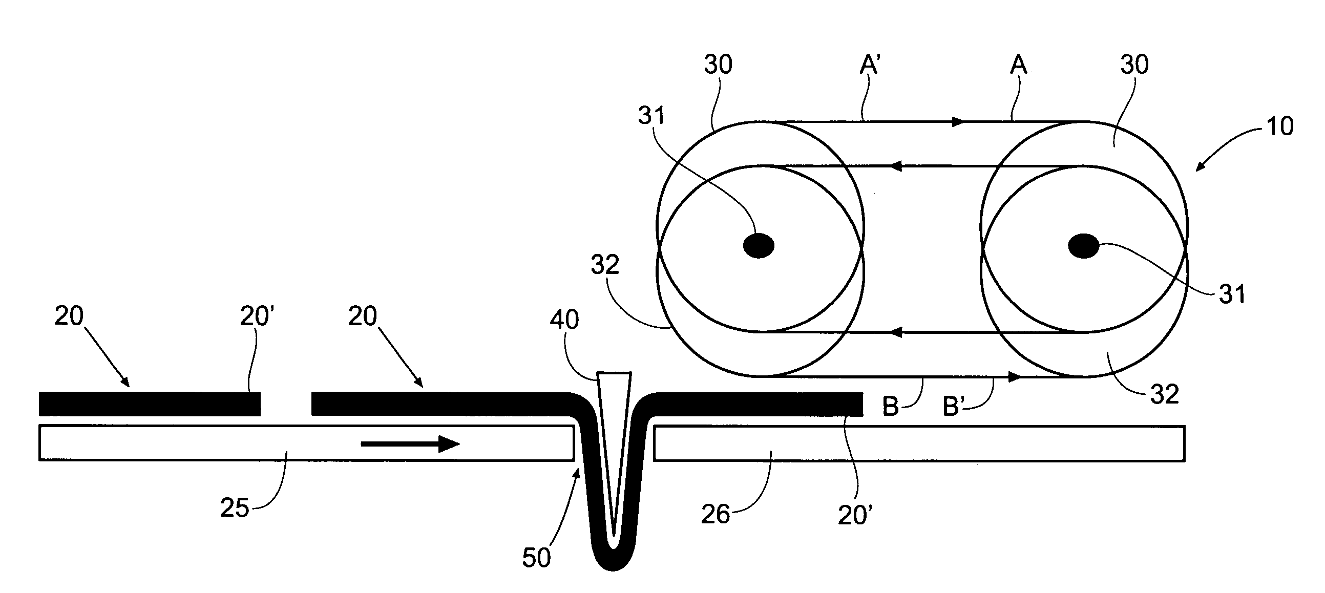
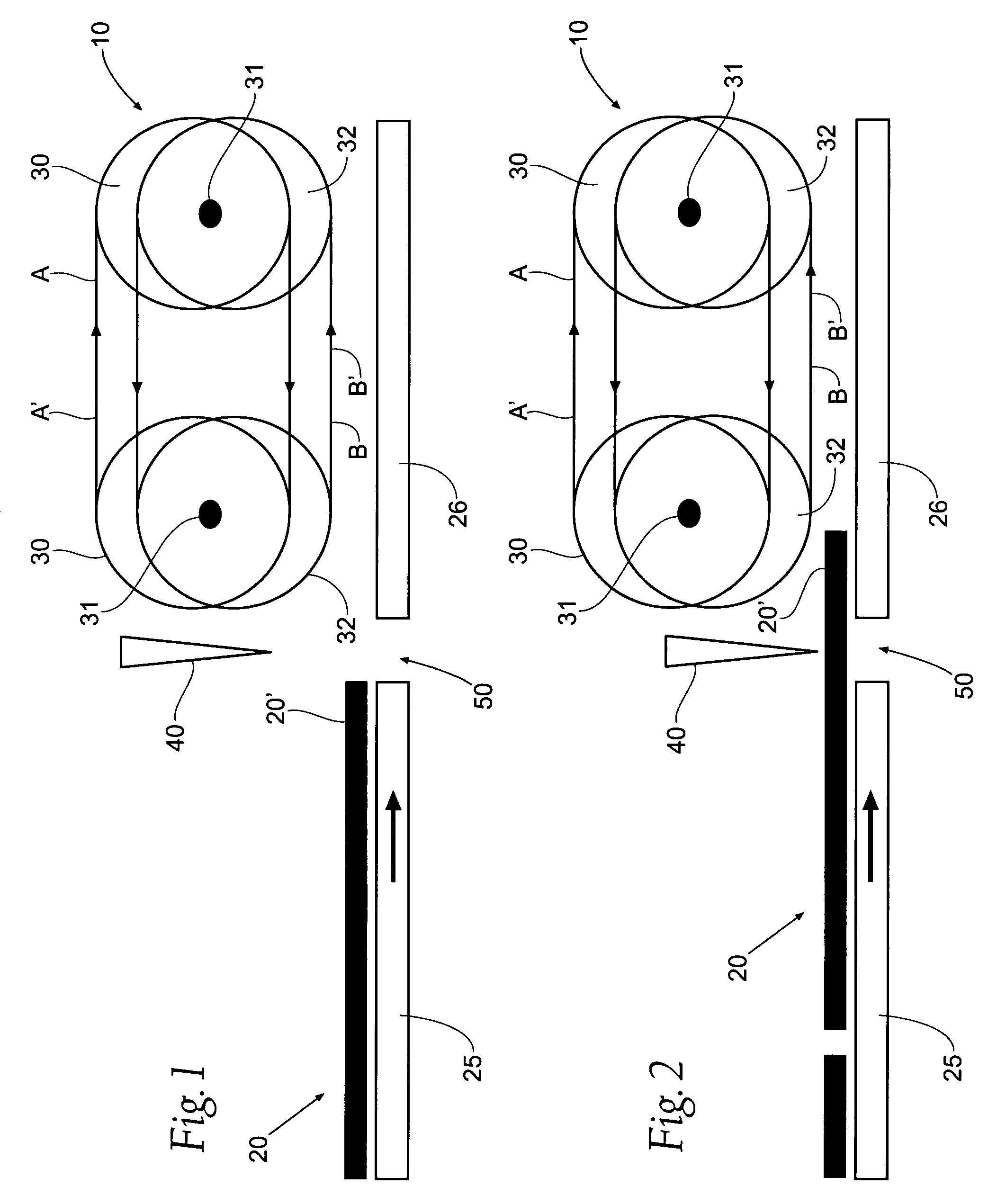
[0036]Referring now FIG. 1, a side view is shown of an apparatus 10 for reversing direction of an article 20, showing a first belt B operating in a first direction B′, a second belt A operating in a second direction A′. The article 20, which may be a diaper in a prefer...


PUM

PropertyMeasurementUnit
speedaaaaaaaaaa
time periodaaaaaaaaaa
reversal forcesaaaaaaaaaa

Abstract

A method of reversing direction of an article, or of speeding up or slowing down an article is disclosed by engaging an article with a first belt to move the article in a first direction; disengaging the article from the first belt; and then engaging the article with a second belt to move the article at a different speed. An apparatus to change speed of an article is also disclosed by a first belt rotating in a first direction; a second belt rotating in the direction at a second speed; the first belt engaging an article at a first time while the second belt is disengaged with the article, the first belt disengaging the article at a second time, and the second belt engaging the article at a third time while the first belt is disengaged with the article.

Description

RELATED APPLICATIONS[0001]This application is a continuation-in-part of U.S. Ser. No. 11 / 104,316, filed 12 Apr. 2005, now U.S. Pat. No. 7,703,599 which claims the benefit of U.S. Provisional Ser. No. 60 / 563,511, filed 19 Apr. 2004, and entitled “Method and Apparatus for Reversing Direction of an Article”.BACKGROUND OF THE INVENTION[0002]This invention relates to a method and apparatus for rapidly and accurately changing speed and / or reversing direction of a flat article. This invention is not limited to its preferred use, changing speed or reversing direction of a disposable diaper or sheet of paper; but instead the methods and apparatus' of the present invention may be used in wide ranging applications.[0003]During manufacture of disposable diapers of the children's training pant type, or of the adult incontinence type, manufacturers typically process the diapers through a series of steps. For a variety of reasons, during the manufacturing process, it might be necessary to reverse ...

Claims


Application Information

Patent Timeline
Patent Type & Authority Patents(United States)
IPC IPC(8): G06F7/00
CPCA61F13/15764B65H29/16B65H29/68B65H45/18A61F13/15747B65H2301/44522B65H2301/51212B65H2403/514B65H2404/264B65H2404/268B65H2404/2682B65H2513/41B65H2801/57B65H2220/09B65H2220/02B65H2220/08
Inventor MEYER, THOMAS C.JENQUIN, PETER J.
Owner CURT G JOA
Why Eureka
Try Eureka