Recoil reduction apparatus and method for weapon

a technology of reducing apparatus and weapon, which is applied in the field of weapons, can solve the problems of increasing the weight of the weapon, reducing the effectiveness of the weapon, and causing pain or harm to the user,

Inactive Publication Date: 2013-04-16
UNITED STATES OF AMERICA THE AS REPRESENTED BY THE SEC OF THE ARMY
View PDF2 Cites 39 Cited by
  • Summary
  • Abstract
  • Description
  • Claims
  • Application Information

AI Technical Summary

Problems solved by technology

The impact may cause a “kick” that may be felt by the user.
The kick of the weapon may be painful or harmful to the user, particularly when using semi-automatic or automatic weapons.
Many of these devices may not be desirable because they may add too much weight to the weapon or may be too costly.

Method used


Image

  • Recoil reduction apparatus and method for weapon
  • Recoil reduction apparatus and method for weapon
  • Recoil reduction apparatus and method for weapon

Examples


Embodiment Construction

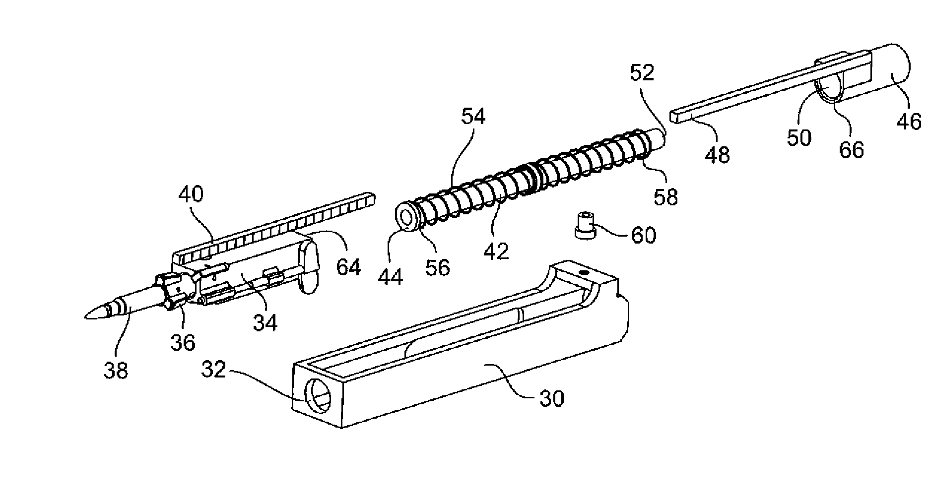
[0017]A recoil reduction apparatus may use a rack and pinion and counter-mass system to partially or completely cancel out the rearward impulse of a weapon's operating group. The operating group of the weapon may impact a forward-moving counterweight. This impact may diminish or eliminate the “kick” produced by the operating group. Peak overall recoil forces may be reduced by coupling the recoil reduction apparatus to a recoil-translating barrel.

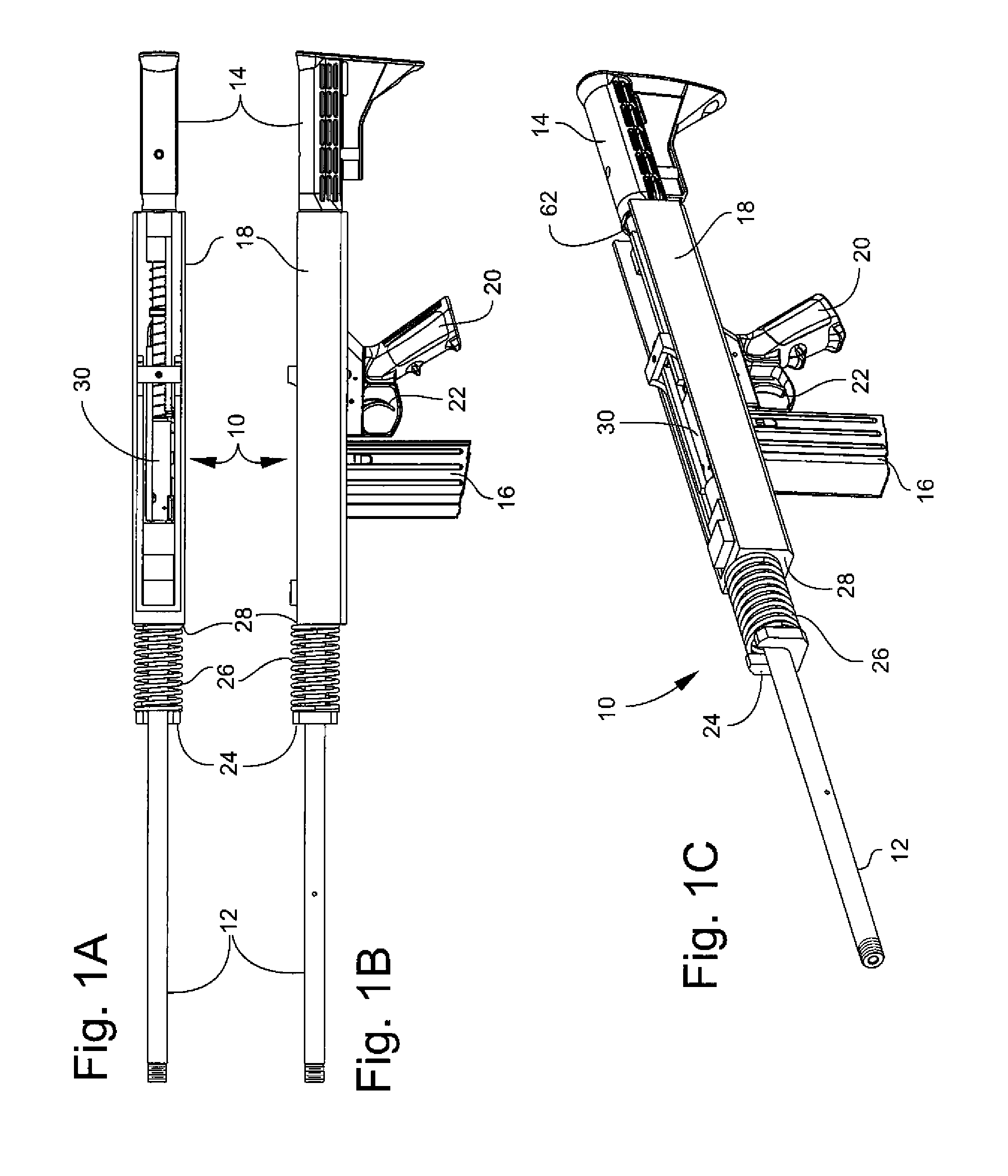
[0018]FIGS. 1A, 1B, and 1C are top, side, and perspective views, respectively, of an embodiment of a weapon 10 in accordance with the invention. Weapon 10 may be, for example, an automatic or semi-automatic weapon of any caliber. Weapon 10 may include a barrel 12, a butt stock 14, a removable ammunition magazine 16, a housing 18, a hand grip 20, and a trigger 22. A receiver 30 may be translatably disposed in housing 18.

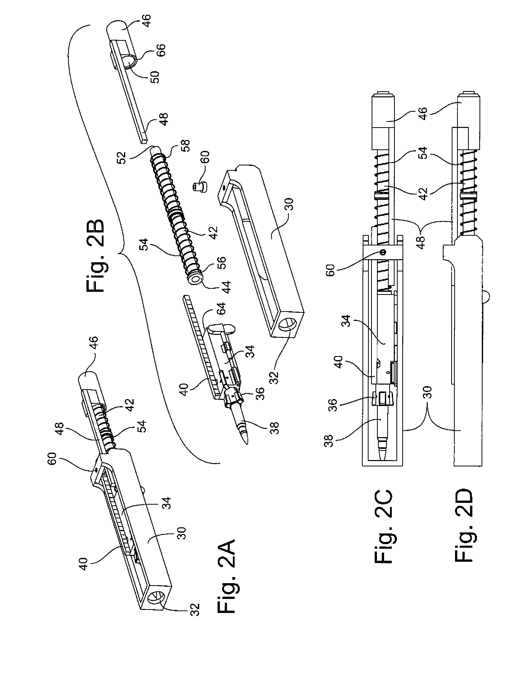
[0019]A barrel 12 may have one end fixed to receiver 30 at area 32 (FIGS. 2A and 2B). Barrel 12 may be translatable through ...


PUM


Abstract

A recoil-reducing weapon may include a housing and a receiver translatably disposed in the housing. A barrel may have one end fixed to the receiver and be translatable with respect to the housing. A spring stop may be fixed to the barrel forward of the housing and a spring may be disposed between the spring stop and a front of the housing. An operating group with a gear rack may be translatably disposed in the receiver. A longitudinal member may have one end fixed to the operating group. A counter-mass may have a second gear rack and an opening therein for receiving the longitudinal member. A second spring may be disposed around the longitudinal member. One end of the second spring may bear against the operating group and another end of the second spring may bear against the counter-mass. A pinion gear may be rotatably fixed to the receiver and operable to mesh with the gear rack and the second gear rack.

Description

STATEMENT OF GOVERNMENT INTEREST[0001]The inventions described herein may be manufactured, used and licensed by or for the U.S. Government for U.S. Government purposes.CROSS-REFERENCE TO RELATED APPLICATIONS[0002]This application is related to U.S. patent application Ser. No. 12 / 607,164 entitled “Apparatus and Method for Gun Recoil Mitigation,” both of which have the same assignee.BACKGROUND OF THE INVENTION[0003]The invention relates in general to weapons and in particular to recoil reduction of weapons.[0004]Traditional weapons may include an operating group, which may include a bolt carrier and its subcomponents, that recoils towards the user in order to cycle the weapon. Typically, the operating group may impact a surface at the end of its stroke. The impact may cause a “kick” that may be felt by the user. In some instances, many rounds of ammunition may be fired by an individual in a short period of time. The kick of the weapon may be painful or harmful to the user, particularl...

Claims


Application Information

Patent Timeline
Patent Type & Authority Patents(United States)
IPC IPC(8): F41A5/10
CPCF41A5/10F41A1/08F41A3/88F41A5/34
Inventor LUKMAN, HANSENCONNOLLY, JAMES R.RUSSELL, KEVIN
Owner UNITED STATES OF AMERICA THE AS REPRESENTED BY THE SEC OF THE ARMY
Why Eureka
Try Eureka