Gas turbine engine composite blade

a technology of composite blades and gas turbine engines, applied in the direction of machines/engines, liquid fuel engines, other domestic articles, etc., can solve the problem that composite fan blades do not exhibit the desired interlaminar shear strength

Active Publication Date: 2013-04-16
HAMILTON SUNDSTRAND CORP
View PDF16 Cites 12 Cited by
  • Summary
  • Abstract
  • Description
  • Claims
  • Application Information

AI Technical Summary

Benefits of technology

[0004]A method of manufacturing a composite airfoil is disclosed that includes providing a fibrous preform core. The fibrous preform core is covered in at least one dry woven layer to provide a skin. The covered fibrous preform core is inserted into a mold cavity. The covered fibrous preform core is impregnated with resin in the mold to produce the composite airfoil. A total skin thickness is less than a core thickness at a central portion of the composite airfoil.

Problems solved by technology

In particular, fan blades must withstand two failure modes experienced during ingestion of foreign objects: interlaminar shear failure and in-plane failure under severe loads induced by the foreign object impact.
Fan blades constructed from composite cores wrapped in composite layers have been suggested in the art; however, these composite fan blades do not exhibit desired interlaminar shear strength.

Method used


Image

  • Gas turbine engine composite blade
  • Gas turbine engine composite blade

Examples


Embodiment Construction

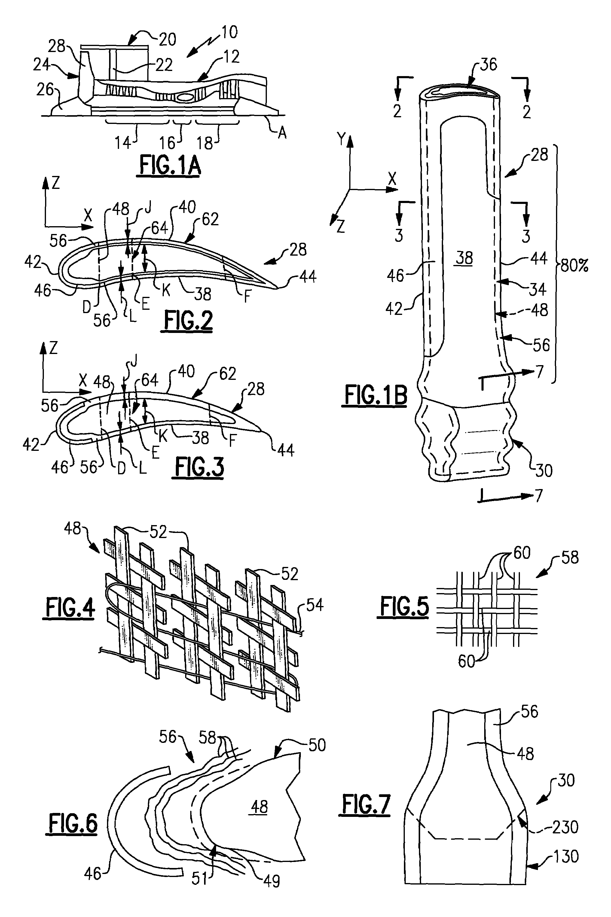
[0015]A gas turbine engine 10 is schematically shown in FIG. 1A. The engine 10 includes a core 12 having a compressor section 14, a combustion section 16 and a turbine section 18. A fan case 20 is supported on the core 12 by flow exit guide vanes 22. The fan case 20 houses a fan section 24 in front of the core 12 that includes multiple circumferentially arranged fan blades 28 and a nose cone 26. The compressor, turbine and fan sections 14, 18, 24 are rotatable about an axis A.

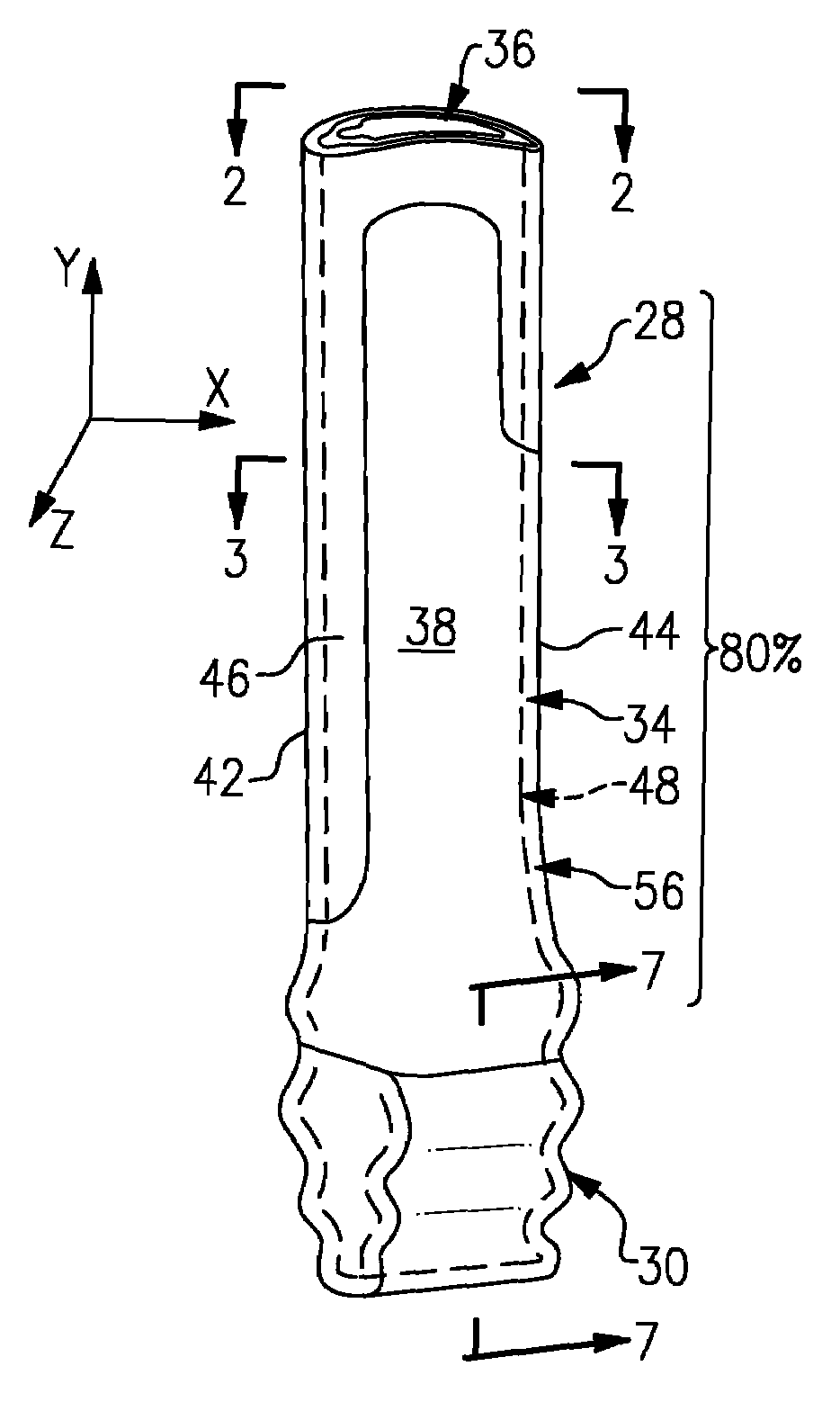
[0016]An example fan blade 28 is schematically shown in FIG. 1B. The fan blade 28 includes an airfoil 34 longitudinally extending from a root 30 in a radial direction Y to a tip 36. An in-plane thickness of the airfoil 34 corresponds to a through-plane direction Z that is generally perpendicular to a chord-wise direction X and the longitudinal direction Y. The airfoil 34 includes opposing sides 38, 40 extending in the chord-wise direction X that respectively provide concave and convex surfaces. Leading and trai...


PUM

PropertyMeasurementUnit
in-plane thicknessaaaaaaaaaa
thicknessaaaaaaaaaa
thicknessaaaaaaaaaa

Abstract

The disclosed composite airfoil includes a three-dimensional composite core extending longitudinally and having a chord-wise direction. The core has a core in-plane thickness extending between opposing sides in a through-plane direction generally perpendicular to the chord-wise and longitudinal directions. A composite skin covers the opposing sides and has an exterior surface providing an airfoil contour. The skin includes a total skin in-plane thickness corresponding to a sum of thicknesses through the skin in the through-plane direction from each of the opposing sides to their adjoining exterior surface. A sum of the core in-plane and total skin in-plane thicknesses at a central portion of the composite airfoil is a total in-plane thickness. The total skin in-plane thickness at the central portion is less than 50% of the total in-plane thickness.

Description

BACKGROUND[0001]This disclosure relates to composite blades. In one example, this disclosure relates to a composite fan blade for a gas turbine engine.[0002]One type of typical gas turbine engine for commercial aircraft applications includes a fan section at an inlet of the engine. It is desirable to design lighter engines, including lighter fan sections, to improve fuel economy. To this end, the use of composite fan blades in the fan section has become more prevalent.[0003]The fan section is designed to withstand ingestion of foreign objects to some degree, such as bird strikes. In particular, fan blades must withstand two failure modes experienced during ingestion of foreign objects: interlaminar shear failure and in-plane failure under severe loads induced by the foreign object impact. Fan blades constructed from composite cores wrapped in composite layers have been suggested in the art; however, these composite fan blades do not exhibit desired interlaminar shear strength.SUMMAR...

Claims


Application Information

Patent Timeline
Patent Type & Authority Patents(United States)
IPC IPC(8): F01D5/28
CPCB29C70/24B29C70/48B29C70/865F01D5/282B29C33/18B29K2707/04F05D2300/603F05D2300/6012B29L2031/08F04D29/324F05D2240/303
Inventor HUTH, BRIAN P.ALEXANDER, PHILLIPKLINETOB, CARL BRIANPARKIN, MICHAELNAIK, RAJIV A.
Owner HAMILTON SUNDSTRAND CORP
Why Eureka
Try Eureka