Method and system for removing an antiferromagnetic seed structure

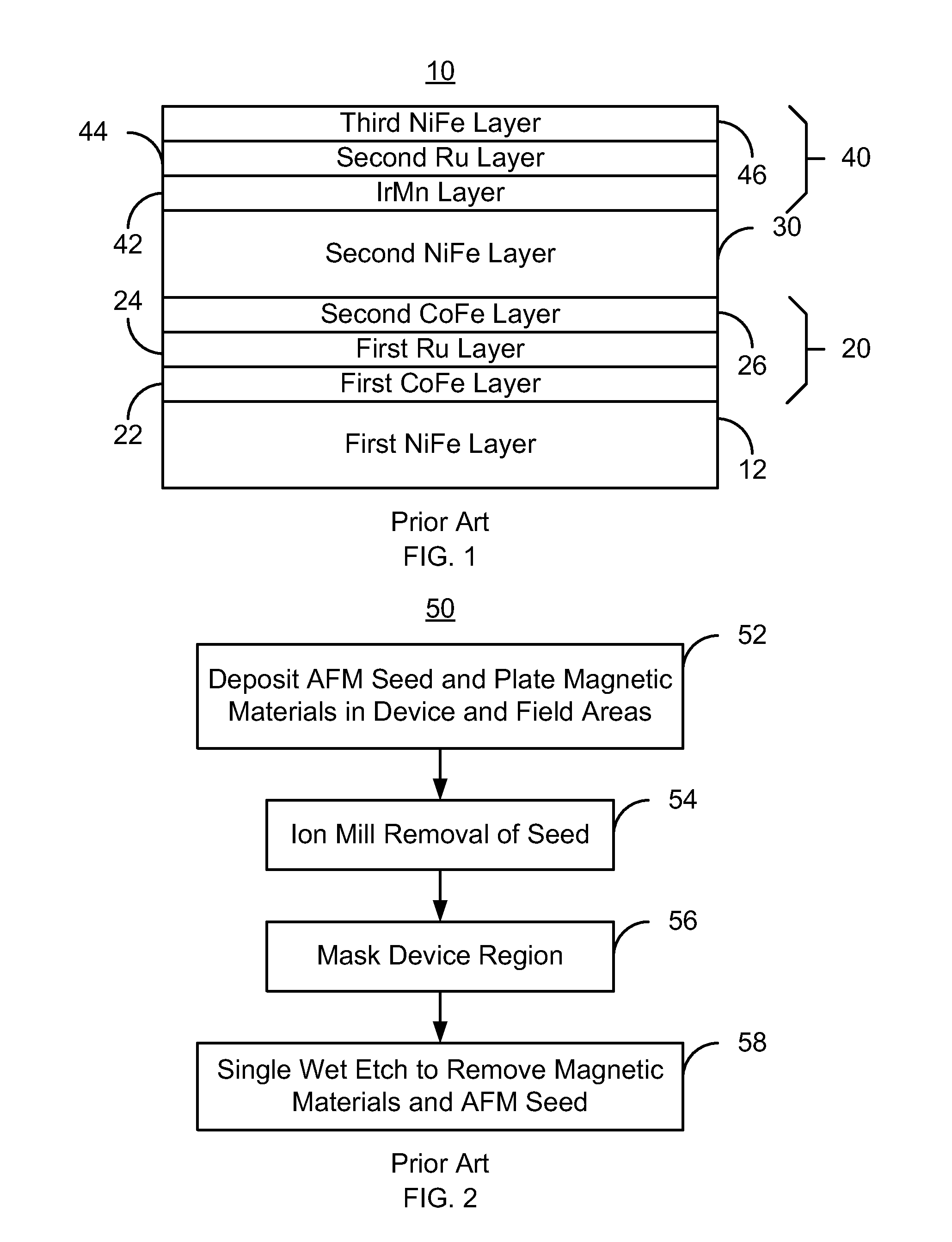
a seed structure and antiferromagnetic technology, applied in the field of methods and systems for removing antiferromagnetic seed structures, can solve the problems of affecting the operation of the magnetic transducer, irmn is only partially soluble in these etchants, and single wet etch is usually unable to adequately remove the afm seed structur

Inactive Publication Date: 2013-04-16
WESTERN DIGITAL TECH INC
View PDF13 Cites 148 Cited by
  • Summary
  • Abstract
  • Description
  • Claims
  • Application Information

AI Technical Summary

Benefits of technology

[0007]FIG. 2 depicts conventional method for fabricating a m

Problems solved by technology

Although such conventional methods may be used, the single wet etch is usually unable to adequately remove the AFM seed structure 10.
Further, IrMn is only partially so

Method used


Image

  • Method and system for removing an antiferromagnetic seed structure
  • Method and system for removing an antiferromagnetic seed structure
  • Method and system for removing an antiferromagnetic seed structure

Examples


Embodiment Construction

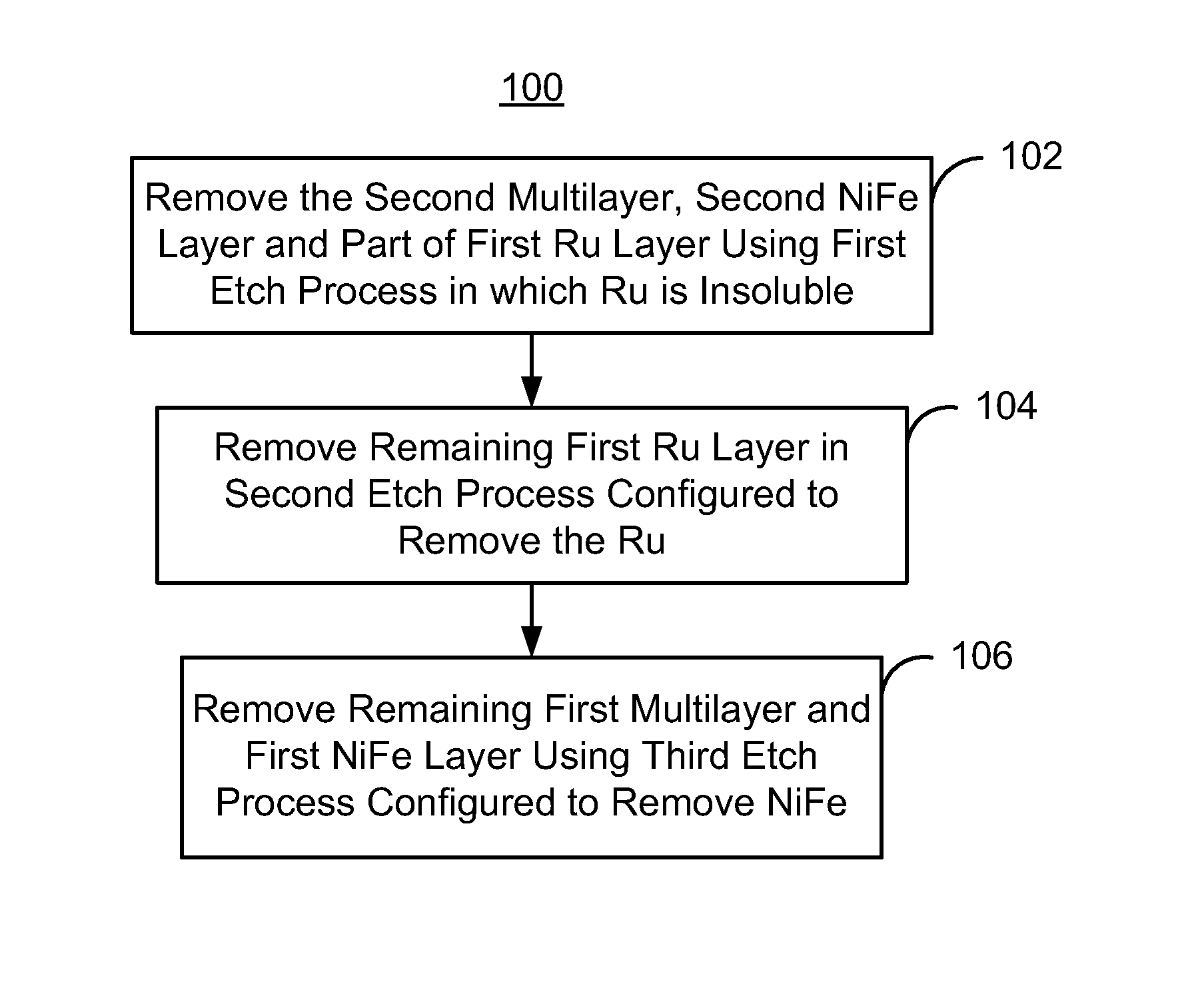
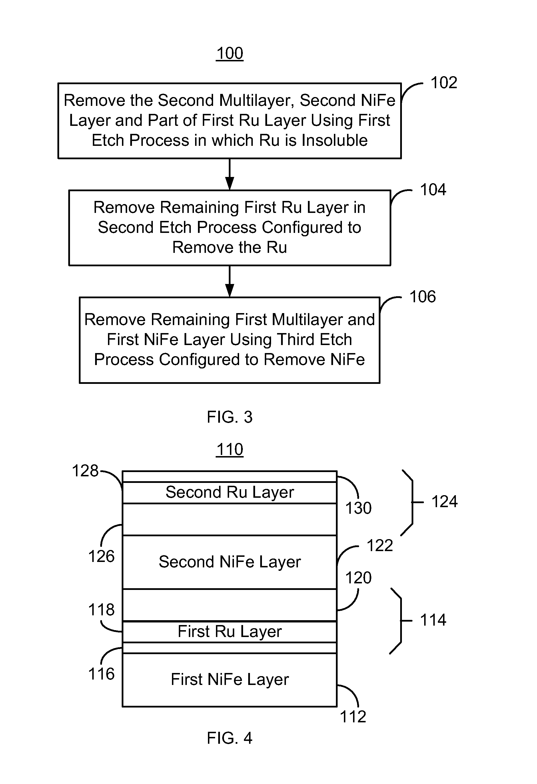
[0012]FIG. 3 depicts an exemplary embodiment of a method 100 for removing an antiferromagnetic (AFM) seed structure that has been used in fabricating a portion of a magnetic transducer. For simplicity, some steps may be omitted, combined, and / or interleaved. The method 100 also may commence after formation of other structures of the read and / or write transducer. FIGS. 4-7 depict an exemplary embodiment of an AFM seed structure 110 removed using the method 100. For clarity, FIGS. 4-7 are not to scale. The method 100 is also described in the context of the AFM seed structure 110 depicted in FIGS. 4-7. The AFM seed structure 110 may be used in a transducer. However, the method 100 may be used to fabricate multiple structures and / or transducer at substantially the same time. The method 100 and AFM seed structure 110 are also described in the context of particular layers. However, in some embodiments, such layers may include sub-layer(s).

[0013]FIG. 4 depicts the AFM seed structure 110 be...


PUM

PropertyMeasurementUnit
Speedaaaaaaaaaa
Speedaaaaaaaaaa
Percent by volumeaaaaaaaaaa

Abstract

A method for fabricating a transducer on a substrate is described. The transducer includes an antiferromagnetic seed structure. The antiferromagnetic seed structure includes a first NiFe layer, a first multilayer including a first Ru layer, a second NiFe layer, and a second multilayer including a second Ru layer. The second multilayer, the second NiFe layer and part of the first Ru layer are removed using a first wet etch, which uses a first etchant combination to remove NiFe and in which Ru is insoluble. The second Ru layer is removed through lift-off due to etching of the second NiFe layer. A remainder of the first Ru layer is removed through a second wet etch, which uses a second etchant combination to remove Ru. A remaining portion of the first multilayer and the first NiFe layer are removed through a third etch, which uses a third etchant combination that removes NiFe.

Description

BACKGROUND[0001]Antiferromagnetic (AFM) seed layers may be used in fabrication of magnetic recording transducers. FIG. 1 depicts one such conventional AFM seed structure 10. For simplicity, FIG. 1 is not to scale. The AFM seed structure 10 includes a first NiFe layer 12, a first multilayer 20, a second NiFe layer 30, and a second multilayer 40. The first multilayer 20 includes a first Ru layer 24 sandwiched between a first CoFe layer 22 and a second CoFe layer 26. The second multilayer 40 includes a second Ru layer 44 sandwiched between an IrMn layer 42 and a third NiFe layer 46. When the conventional AFM seed structure 10 is used as a seed structure for plated magnetic shield and / or pole materials, the resulting magnetic transducer may have improved performance.[0002]FIG. 2 depicts a conventional method 50 for fabricating a magnetic recording transducer using a conventional AFM seed structure. For simplicity, steps may be omitted, combined, or include substeps. The AFM seed structu...

Claims


Application Information

Patent Timeline
IPC IPC(8): B44C1/22
CPCG11B5/3163G11B5/3906G11B5/3929G01R33/09G01R33/093H01L43/12H10N50/01
Inventor SU, WENCHENGZHOU, ZHIGANGANG, JANEJIANG, MING
Owner WESTERN DIGITAL TECH INC
Why Eureka
Try Eureka