Actuator, drive device, and imaging device

a drive device and actuator technology, applied in the direction of instruments, machines/engines, television systems, etc., to achieve the effect of efficient deformation, high degree of freedom in design, and highly accurate control of the amount of deformation of the movable par

Inactive Publication Date: 2013-04-16
KONICA MINOLTA OPTO
View PDF9 Cites 15 Cited by
  • Summary
  • Abstract
  • Description
  • Claims
  • Application Information

AI Technical Summary

Benefits of technology

[0016]In the actuator according to the first aspect, the portion generating force in accordance with heating and the portion generating heat are separately provided, and therefore an actuator allowing a control of the displacement and configured to offer a high degree of freedom in designing can be provided.
[0017]In the actuator according to the second aspect, a sufficient amount of deformation of the heat generating portion and a sufficient amount of change in the electrical resistance occur relative to the amount of deformation of the movable part, thus allowing a highly accurate control of the amount of deformation of the movable part.
[0018]In the actuator according to the third aspect, the movable part is largely deformed in response to a current application, thus enabling the movable part to be efficiently deformed.
[0019]In the actuator according to the fourth aspect, a manufacturing cost can be reduced.
[0020]In the drive device according to the fifth aspect, a drive device can be achieved that includes an actuator allowing a control of displacement and configured to offer a high degree of freedom in designing.
[0021]In the imaging device according to the sixth aspect, an imaging device can be achieved that includes an actuator allowing a control of displacement and configured to offer a high degree of freedom in designing.

Problems solved by technology

More and more downsizing and weight reduction are constantly required of such a portable electronic device, which inevitably requires downsizing and weight reduction of a camera module.
In the actuator adopting the shape-memory alloy, the shape-memory alloy is electrically heated to be thereby expanded and contracted, thus causing a displacement.

Method used


Image

  • Actuator, drive device, and imaging device
  • Actuator, drive device, and imaging device
  • Actuator, drive device, and imaging device

Examples


Embodiment Construction

[0051]In the following, one embodiment of the present invention will be described with reference to the accompanying drawings.

[0052]

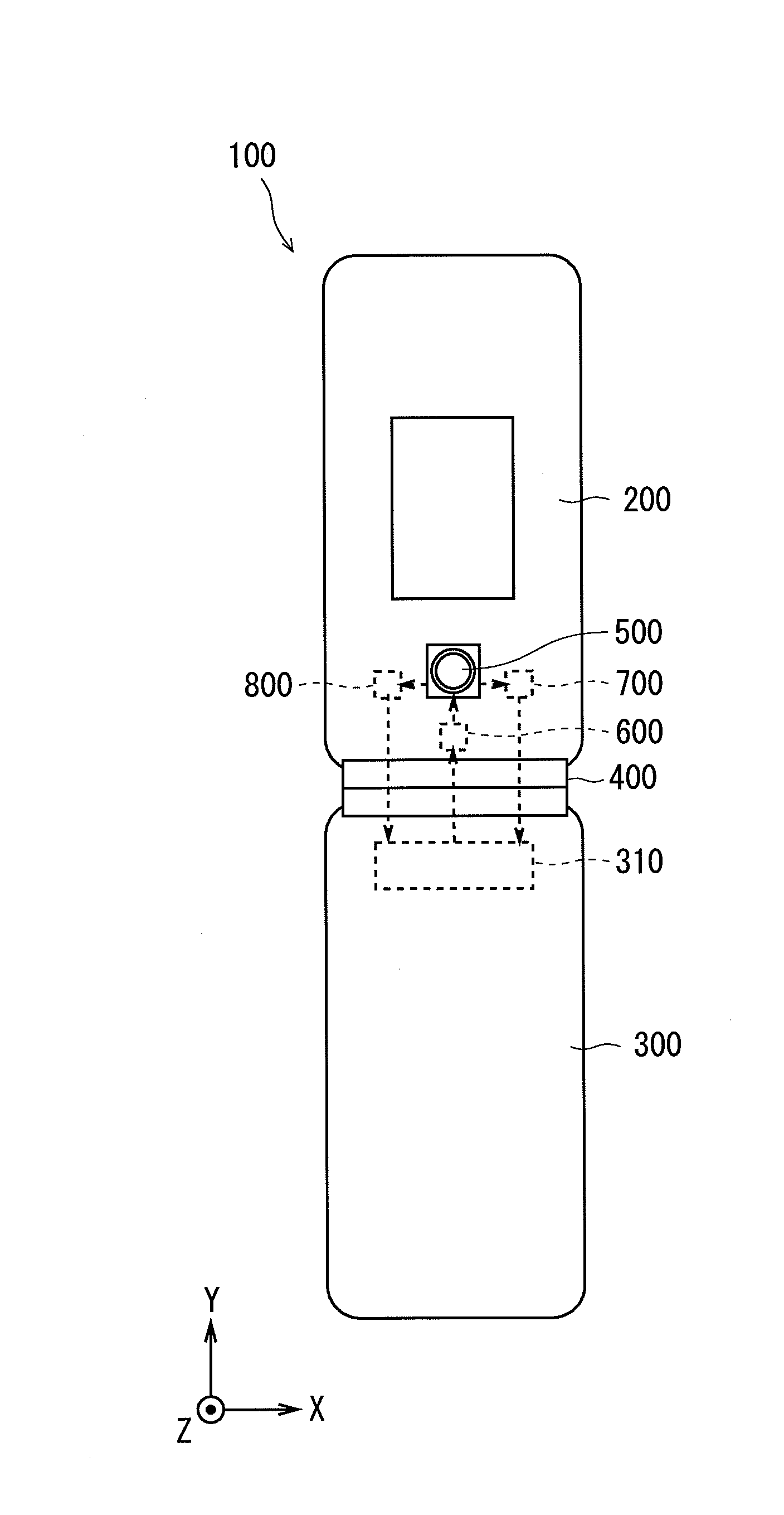
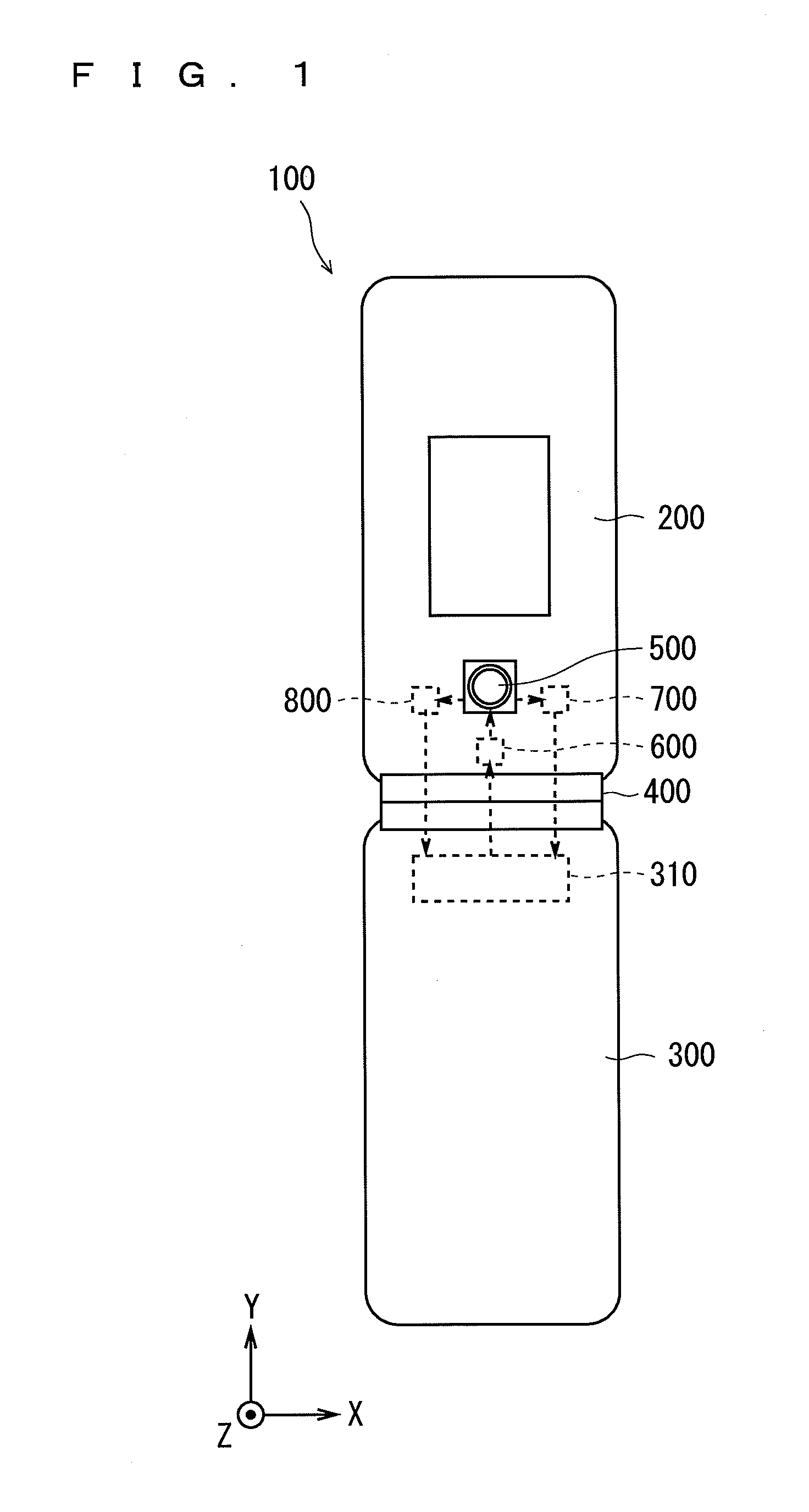
[0053]FIG. 1 is a diagram schematically showing an outline configuration of a mobile phone 100 having installed therein a camera module 500 according to one embodiment of the present invention. In FIG. 1 and subsequent figures, for clarification of an orientation relationship, three orthogonal X, Y, and Z axes are shown as appropriate.

[0054]As shown in FIG. 1, the mobile phone 100 is configured as a flip mobile phone, and includes a first housing 200, a second housing 300, and a hinge part 400. Each of the first housing 200 and the second housing 300 has a substantially rectangular parallelepiped plate-like shape, and functions as a housing for accommodating various electronic members. To be specific, the first housing 200 has the camera module 500 and a display (not shown), and the second housing 300 has a control section for electrically controlling t...


PUM


Abstract

An object of the present invention is to provide an actuator allowing a control of displacement and configured to offer a high degree of freedom in designing, and a drive device and an imaging device including the actuator. To achieve the object, an actuator is adopted including a movable part deformable in accordance with heat generation and a control section controlling the amount of deformation of the movable part. In the actuator, the movable part is structured with a plurality of portions including a base portion, a force generating portion, and a heat generating portion being stacked, the force generating portion generating force in accordance with heating, the heat generating portion generating heat in accordance with a current supply. The control section controls the amount of deformation of the movable part by controlling the current supply to the heat generating portion based on an electrical resistance in the heat generating portion.

Description

RELATED APPLICATIONS[0001]This application is a U.S. National Phase Application under 35 USC 371 of International Application PCT / JP2010 / 054434 filed Mar. 16, 2010[0002]This application claims the priority of Japanese application No. 2008-074102 filed Mar. 25, 2009, the entire content of which is hereby incorporated by reference.TECHNICAL FIELD[0003]The present invention relates to an actuator, and a drive device and an imaging device including the actuator.BACKGROUND ART[0004]In recent years, in a portable electronic device typified by a mobile phone, a digital camera is provided as a standard function. More and more downsizing and weight reduction are constantly required of such a portable electronic device, which inevitably requires downsizing and weight reduction of a camera module. However, in the camera module installed in the portable electronic device, there is a demand for enhancement of functions including an auto-focus function, a camera shake correction function, and the...

Claims


Application Information

Patent Timeline
Patent Type & Authority Patents(United States)
IPC IPC(8): H04N5/232H01L21/00H04N5/228G03B15/00G03B17/00
CPCF03G7/065
Inventor KOSAKA, AKIRATANIMURA, YASUTAKAMATSUO, TAKASHIYAMAMOTO, NATSUKI
Owner KONICA MINOLTA OPTO
Why Eureka
Try Eureka