
Device for outputting luminance signal

Inactive Publication Date: 2013-04-16
SILICON INTEGRATED SYSTEMS
View PDF4 Cites 0 Cited by
  • Summary
  • Abstract
  • Description
  • Claims
  • Application Information

AI Technical Summary

Benefits of technology

The technical effect of this patent is to provide a device that can produce a luminance signal.

Problems solved by technology

However, it is difficult to make a precise judgment between the motion condition and the static condition.

Method used


Image

  • Device for outputting luminance signal
  • Device for outputting luminance signal
  • Device for outputting luminance signal

Examples


Embodiment Construction

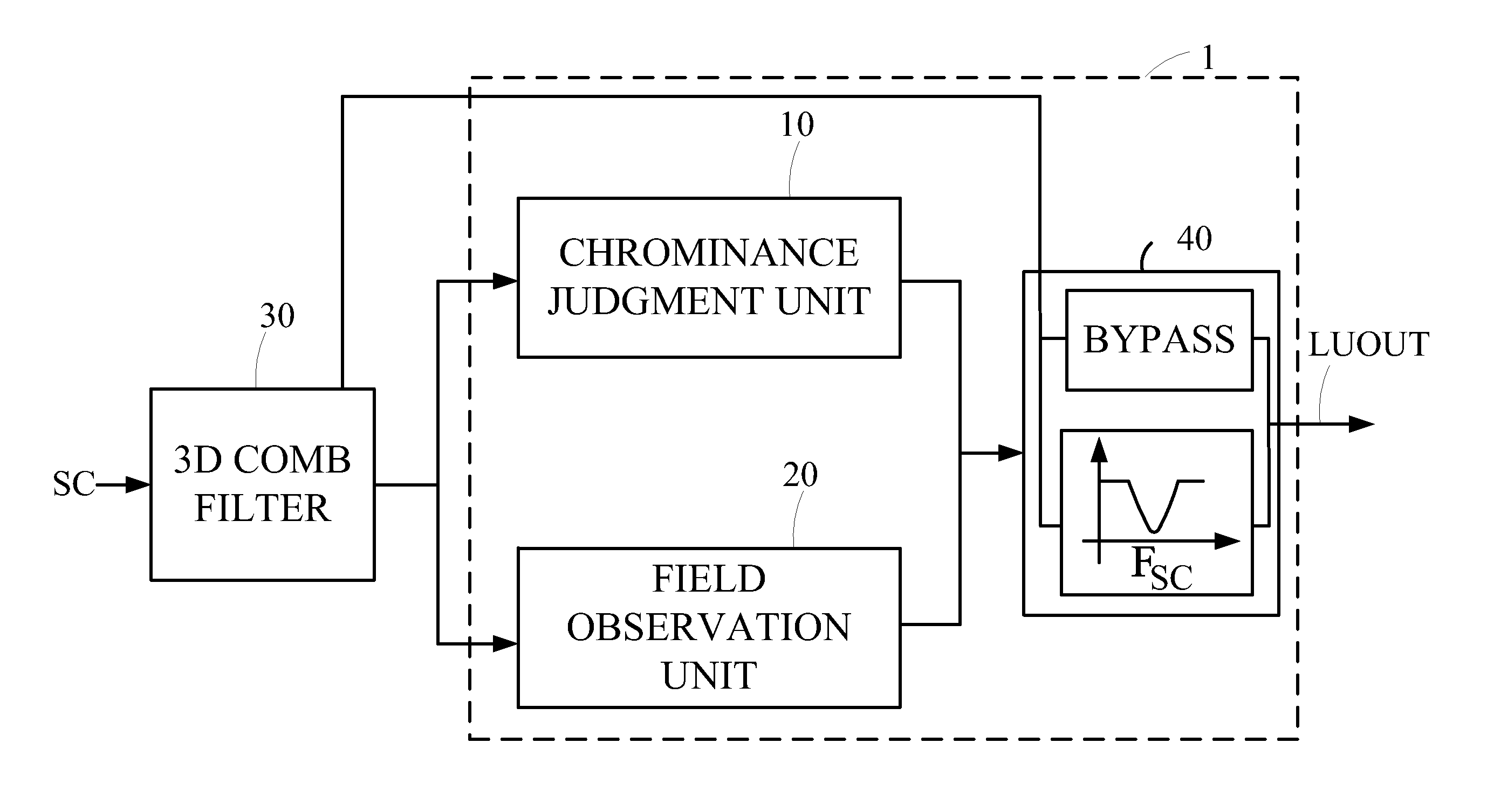
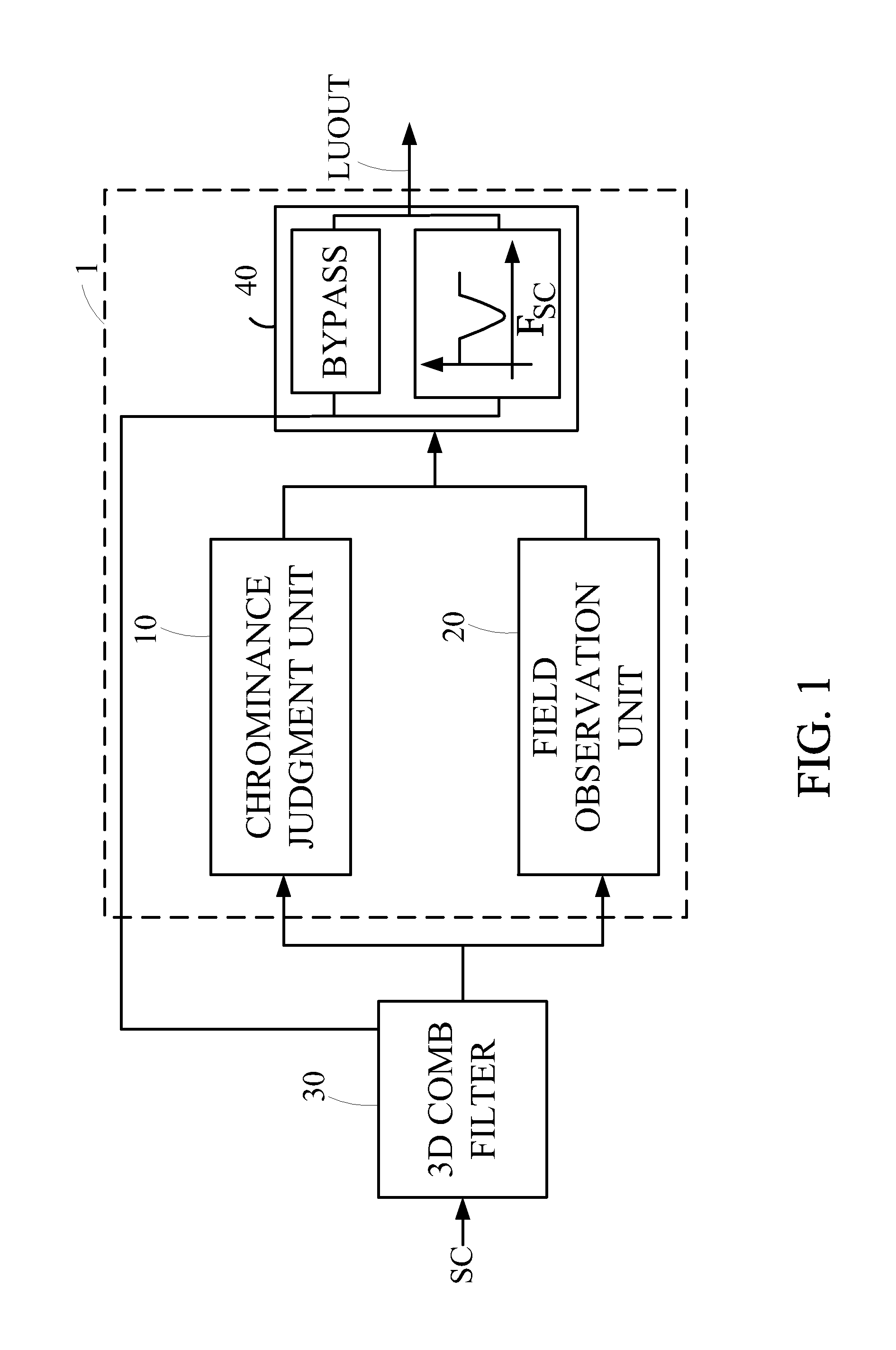
[0012]FIG. 1 is a schematic diagram showing an image processing system has a device 1 for outputting a luminance signal according to an embodiment of the present invention. The image processing system comprises a 3D comb filter 30 and the device 1. The 3D comb filter 30 receives a composite video SC of a frame. The composite video signal SC has a luminance component and a chrominance component which is modulated onto a carrier frequency. A 3D chrominance signal and a 3D luminance signal are extracted from the composite video signal SC by the 3D comb filter 30. In the prior arts, the 3D chrominance signal and the 3D luminance signal from the 3D comb filter 30 are directly served as an output chrominance signal and an output luminance signal. However, when the 3D comb filter 30 is wrongly used in a motion condition, the 3D chrominance signal and the 3D luminance signal may be incorrect. The device 1 according to the present invention judges characteristics of the 3D chrominance signal...


PUM


Abstract

A device for outputting a luminance signal is disclosed. The device includes a chrominance judgment unit, a field observation unit, and an output unit. The chrominance judgment unit and the field observation unit are used to determine whether a 3D luminance signal is affected. The output unit outputs a resultant luminance signal according to the determination results of the chrominance judgment unit and the field observation unit. According to the present invention, the resultant luminance signal can be accurately obtained by judging characteristics of the 3D luminance signal and a 3D chrominance signal even if a 3D comb filter is wrongly used in a motion condition.

Description

TECHNICAL FIELD OF THE INVENTION[0001]The present invention relates to a device, more particularly, to a device for outputting a luminance signal.BACKGROUND OF THE INVENTION[0002]A composite video signal comprises a luminance signal (Y) and a chrominance signal (C). A comb filter is commonly used to separate the luminance signal and the chrominance signal from the composite video signal. The process of separating the luminance signal and the chrominance signal is referred to as a Y / C separation.[0003]There are three types of comb filters used to separate the composite video signal. The three types of comb filters are classified into a one-dimensional (1D) comb filter, a two-dimensional (2D) comb filter and a three-dimensional (3D) comb filter. The 1D comb filter and the 2D comb filter are referred to as a type of non-3D comb filter. In general, the non-3D comb filter is used to separate the luminance signal and the chrominance signal when an image is under a motion condition, and th...

Claims


Application Information

Patent Timeline
IPC IPC(8): H04N9/78
CPCH04N9/78
Inventor TAI, ALBERT HUAWEI, FENG CHILIU, HENG YI
Owner SILICON INTEGRATED SYSTEMS
Features
  • Generate Ideas
  • Intellectual Property
  • Life Sciences
  • Materials
  • Tech Scout
  • Unparalleled Data Quality
  • Higher Quality Content
  • 60% Fewer Hallucinations
Learn More