Digital image system and method for implementing an adaptive demosaicing method

a digital image system and demosaicing technology, applied in the field of digital image processing, can solve the problems of further reducing the appearance of the “zipper effect” and achieve the effects of reducing the imbalance between luminance pixels, and being easy to implement in hardwar

Inactive Publication Date: 2006-08-08
APTINA IMAGING CORP
View PDF32 Cites 110 Cited by
  • Summary
  • Abstract
  • Description
  • Claims
  • Application Information

AI Technical Summary

Benefits of technology

[0017]The present invention provides an adaptive demosaicing method that interpolates each pixel location by separately considering the degree of change (e.g., the gradient, the Laplacian or other measure of the degree of change) in both the horizontal and vertical directions in at least two of the color planes. The adaptive demosaicing algorithm uses a voting scheme to determine the direction of interpolation at each pixel location. Each color plane votes either horizontal or vertical based on a comparison between the vertical and horizontal components of the degree of change in that color plane. In some embodiments, votes are counted from the neighborhood pixels as well as from measurements taken at the pixel location itself In one embodiment, the direction of interpolation is applied only to the luminance color plane. Once the luminance plane is fully interpolated, the chrominance planes are filled in by a simple bilinear or median interpolation of difference chrominance values. Enhancements to the adaptive demosaicing algorithm permit adaptive smoothing and sharpening. For example the adaptive demosaicing algorithm is capable of adapting to low-light level (i.e., noisy) images, and reducing the imbalance between luminance pixels.
[0018]Since the adaptive demosaicing algorithm requires only additions, subtractions, shifts and comparisons, all of which are easy to implement in hardware, the adaptive demosaicing algorithm reduces the hardware complexity present in previous demosaicing methods. In addition, the adaptive demosaicing algorithm further reduces the appearance of the “zipper effect” in demosaiced images as compared with previous demosaicing methods. Furthermore, the invention provides embodiments with other features and advantages in addition to or in lieu of those discussed above. Many of these features and advantages are apparent from the description below with reference to the following drawings.

Problems solved by technology

In addition, the adaptive demosaicing algorithm further reduces the appearance of the “zipper effect” in demosaiced images as compared with previous demosaicing methods.

Method used


Image

  • Digital image system and method for implementing an adaptive demosaicing method
  • Digital image system and method for implementing an adaptive demosaicing method
  • Digital image system and method for implementing an adaptive demosaicing method

Examples


Embodiment Construction

[0028]The numerous innovative teachings of the present application will be described with particular reference to the exemplary embodiments. However, it should be understood that these embodiments provide only a few examples of the many advantageous uses of the innovative teachings herein. In general, statements made in the specification do not necessarily delimit any of the various claimed inventions. Moreover, some statements may apply to some inventive features, but not to others.

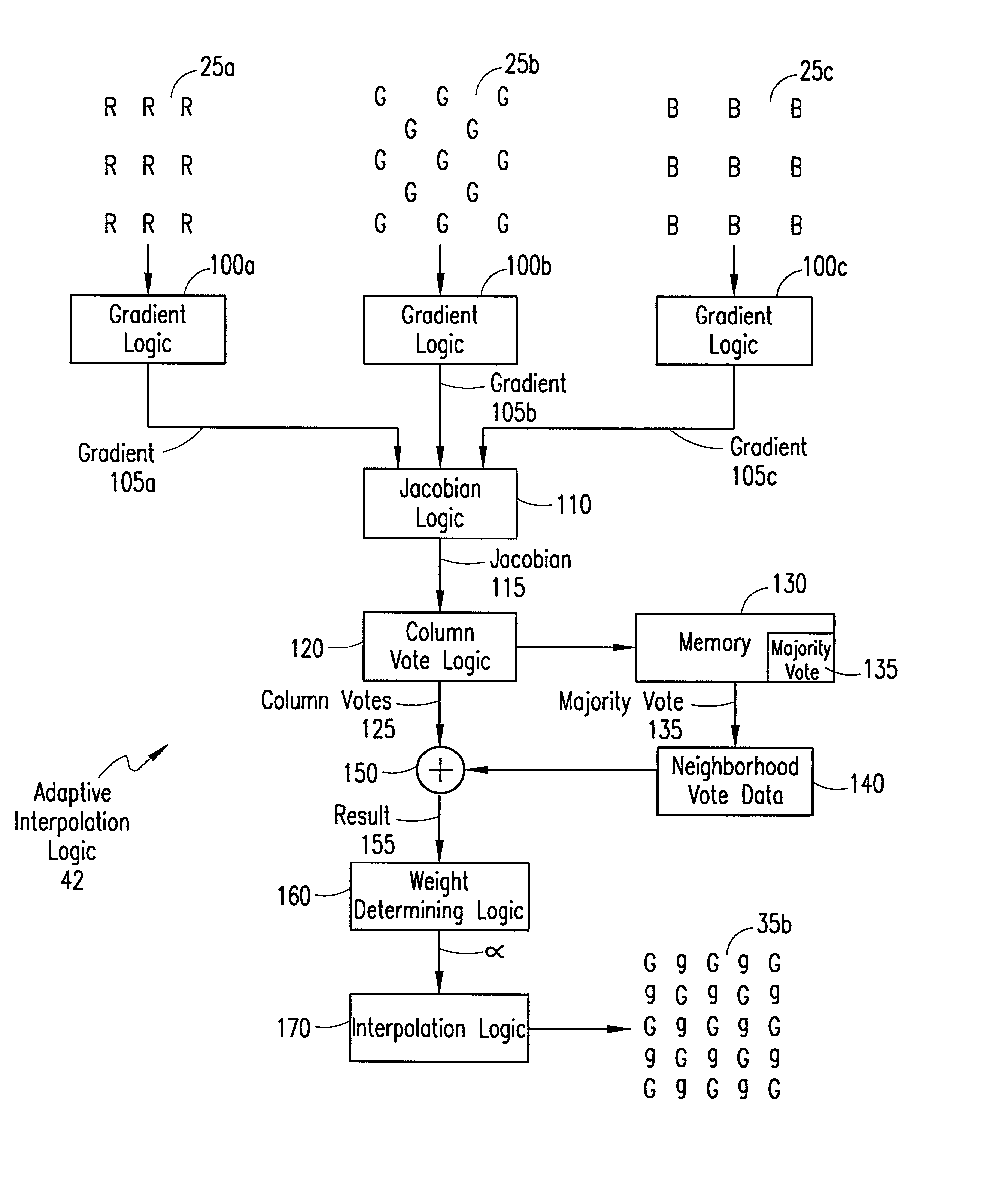
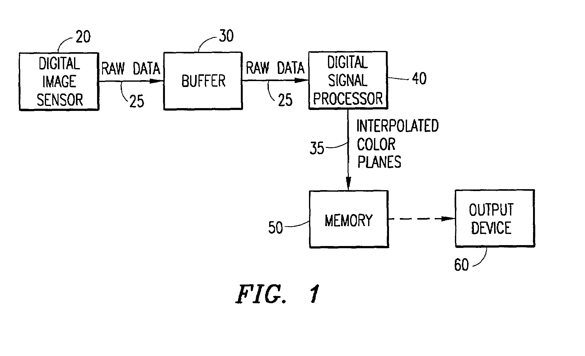
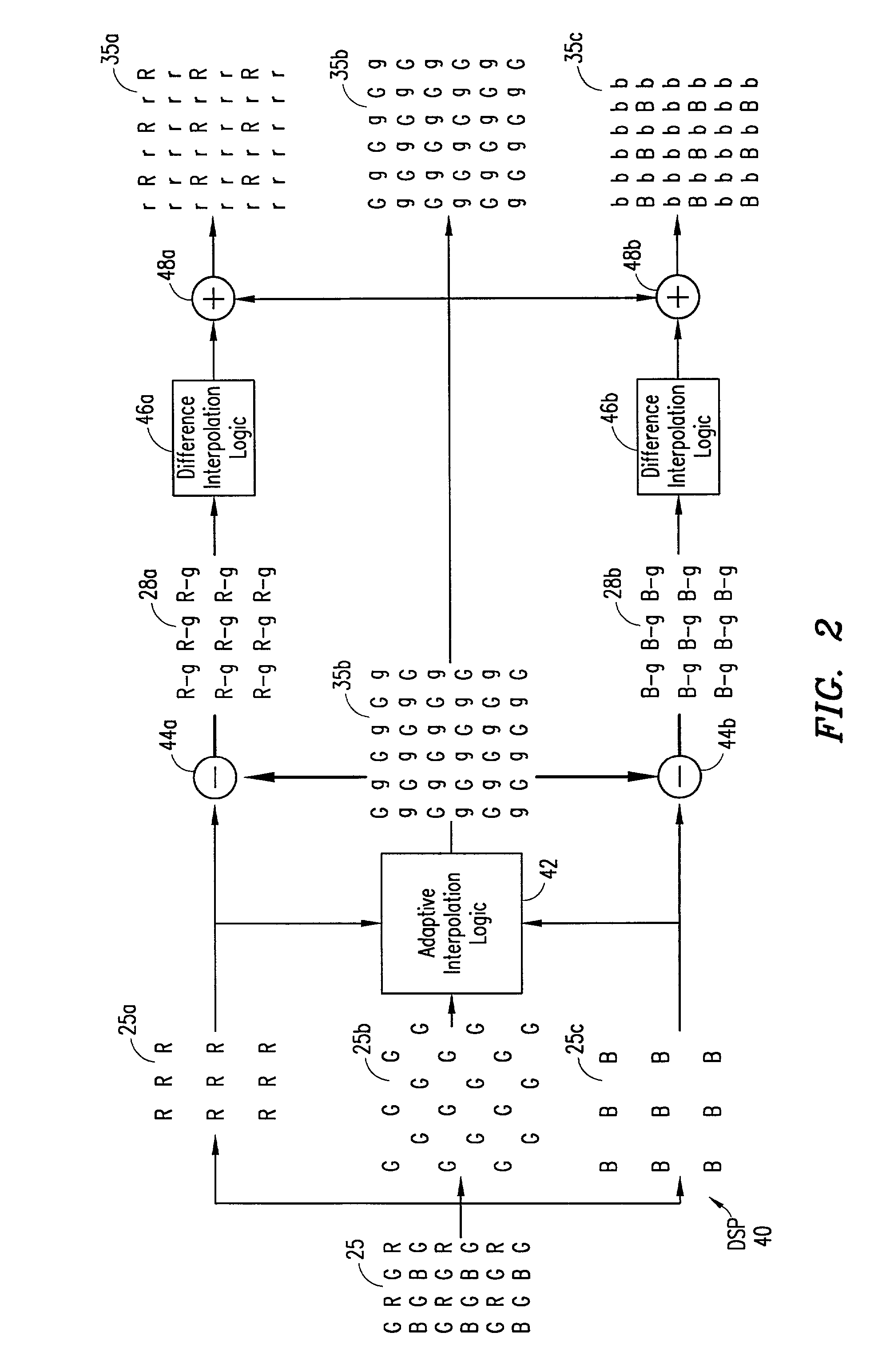
[0029]FIG. 1 shows a digital image system 10 implementing the adaptive demosaicing algorithm 40 in accordance with the present invention. The digital image system 10 can be any digital imaging device, such as a digital camera, video camera, medical imaging device, etc. The digital image system 10 can also be a computer system, such as a personal computer or server, having a memory therein for storing image data. Thus, the adaptive demosaicing algorithm 40 can be within a digital imaging device or a part ...


PUM


Abstract

An adaptive demosaicing method interpolates images based on color edge detection and neighborhood voting. The adaptive demosaicing algorithm uses a voting scheme to determine the direction of interpolation at each missing luminance pixel location. Each color plane votes either horizontal or vertical based on a comparison between the horizontal and vertical components of the degree of change (i.e., gradient, Laplacian or other measure of the degree of change) in that color plane. Votes are counted from the neighborhood pixels as well as from measurements taken at the pixel location itself. Once the luminance plane is fully interpolated, the chrominance planes are filled in by simple bilinear or median interpolation of difference chrominance values. Enhancements to the adaptive demosaicing algorithm permit adaptive smoothing and sharpening.

Description

BACKGROUND OF THE INVENTION[0001]1. Technical Field of the Invention[0002]The present invention relates generally to digital image processing, and particularly to demosaicing methods for interpolating colors at each pixel location.[0003]2. Description of Related Art[0004]Digital color image sensors are predominately of two types: CCDs (Charge Coupled Devices) and CMOS—APS (Complimentary Metal Oxide Semiconductor—Active Pixel Sensors). Both types of sensors typically contain an array of photo-detectors (pixels), arranged in rows and columns, that sample color within an image. Each pixel measures the intensity of light within one or more ranges of wavelengths, corresponding to one or more colors.[0005]In addition, both types of sensors may include a color filter array (CFA), such as the CFA described in U.S. Pat. No. 3,971,065 to Bayer (hereinafter referred to as Bayer), which is hereby incorporated by reference. With the Bayer CFA, each pixel sees only one color: red, green or blue. ...

Claims


Application Information

Patent Timeline
Patent Type & Authority Patents(United States)
IPC IPC(8): H04N5/335G06T3/40H04N1/393H04N1/48H04N1/60H04N9/04H04N9/07
CPCG06T3/4007H04N9/045G06T3/403G06T3/4015H04N23/843H04N25/134
Inventor KAKARALA, RAMAKRISHNABAHARAV, IZHAK
Owner APTINA IMAGING CORP
Why Eureka
Try Eureka