Color display devices

a color display and display device technology, applied in the field of display devices, can solve the problems of poor color brightness and limited whiteness of the rgb color system, and achieve the effect of increasing the color brightness

Active Publication Date: 2013-04-16
E INK CORPORATION
View PDF53 Cites 99 Cited by
  • Summary
  • Abstract
  • Description
  • Claims
  • Application Information

AI Technical Summary

Benefits of technology

[0006]The present invention is directed to further alternative designs of color display devices. The color display of the present invention allows each display cell to display at least four different color states, which enables a significant increase in color brightness (from 50% to more than 3 times in color brightness compared to the RGB type display), while maintaining the non-compromised black and white color states.

Problems solved by technology

However, in general, the RGB color system shows very limited whiteness and poor color brightness.

Method used


Image

  • Color display devices
  • Color display devices
  • Color display devices

Examples


Embodiment Construction

I. Configuration of a Display Device

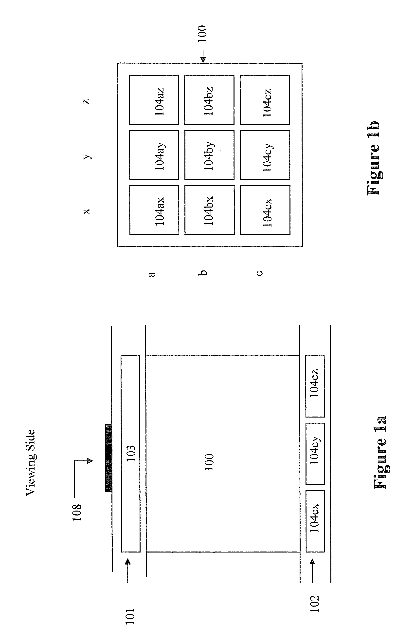
[0036]FIG. 1a depicts a cross-section view of a display cell of a color display device of the present invention. The display cell (100) is sandwiched between a first layer (101) and a second layer (102). The first layer comprises a common electrode (103). The second layer comprises more than one driving electrode (104ax, 104ay, 104az, 104bx, 104by, 104bz, 104cx, 104cy and 104cz). However, in the cross-section view, only the driving electrodes 104cx, 104cy and 104cz are shown.

[0037]In one embodiment, each display cell, as shown in FIG. 1a, represents a single sub-pixel or pixel.

[0038]FIG. 1b depicts the top view of the layer comprising driving electrodes of the display cell of FIG. 1a. As shown, the second layer (102) comprises 3×3 driving electrodes, denoted as 104ax, 104ay, 104az, 104bx, 104by, 104bz, 104cx, 104cy and 104cz. While only a 3×3 grid is shown, the second layer may comprise any grid which is at least 2×2. The size of the driving elect...


PUM

PropertyMeasurementUnit
reflectanceaaaaaaaaaa
optical densityaaaaaaaaaa

Abstract

The present invention is directed to color display devices which are capable of displaying multiple color states. The display device comprises a plurality of display cells, wherein each of said display cells is (a) sandwiched between a first layer comprising a common electrode and a second layer comprising a plurality of driving electrodes, wherein at least one of the driving electrodes is a designated electrode, (b) filled with an electrophoretic fluid comprising at least two types of pigment particles dispersed in a solvent or solvent mixture, and (c) capable of displaying at least four color states. The display device may also comprise hiding layers or a brightness enhancement structure on the viewing side.

Description

[0001]This application claims priority to U.S. Provisional Application No. 61 / 042,180, filed Apr. 3, 2008; the content of which is incorporated herein by reference in its entirety.FIELD OF THE INVENTION[0002]The present invention is directed to display devices in which each display cell is capable of displaying multiple color states. The display device may also comprise blocking layers such as black matrix layers or a brightness enhancement structure on the viewing side.BACKGROUND OF THE INVENTION[0003]Prior technologies relating to reflective color displays have, in general, used red / green / blue (RGB) colors. In the RGB color displays, each pixel is broken down into three or four sub-pixels and each sub-pixel has a red filter, blue filter, green filter or no filter over a black and white reflective medium. By selectively turning sub-pixels on or off, a full color spectrum may be achieved. For example, the white state is achieved by turning on all three RGB sub-pixels. Because each o...

Claims


Application Information

Patent Timeline
Patent Type & Authority Patents(United States)
IPC IPC(8): G02B26/00G09G3/34G02F1/167G02F1/16762
CPCG02F1/167G02F1/133526G02F2203/34G02F2001/1678G02F2001/1676G02F1/16762
Inventor SPRAGUE, ROBERT A.LIN, CRAIG
Owner E INK CORPORATION
Why Eureka
Try Eureka