
Fixing unit with auxiliary heating member and surface recovery member, and image forming apparatus

a technology of fixing unit and fixing member, which is applied in the direction of electrographic process apparatus, instruments, optics, etc., can solve the problems of surface damage of the fixing member, occurrence of image degradation, and state of being roughened, so as to prolong the life of the friction sliding section

Inactive Publication Date: 2013-04-16
KONICA MINOLTA BUSINESS TECH INC
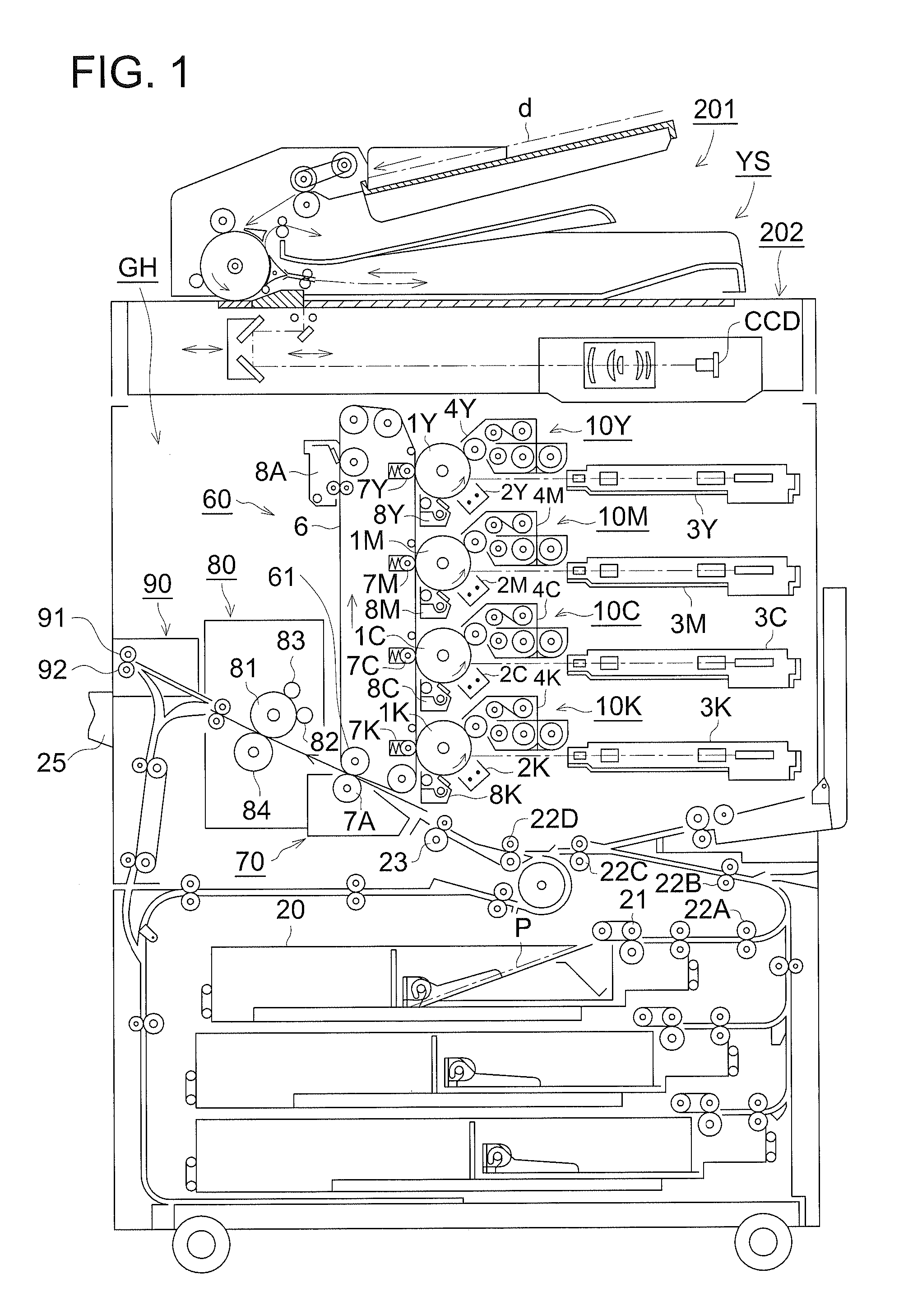
View PDF3 Cites 2 Cited by
  • Summary
  • Abstract
  • Description
  • Claims
  • Application Information

AI Technical Summary

Benefits of technology

The present invention provides a fixing unit that can maintain the recovery function of a friction sliding section for a long time, which helps to recover the surface property of a fixing member and an image fowling apparatus.

Problems solved by technology

As a recording medium is conveyed to the fixing unit in this manner, the surface of the fixing member is damaged by the recording medium and then gradually roughened.
The damage is mainly caused by burrs of both edges of the recording medium produced during cutting of the recording medium.
Especially when recording media of the same size are continuously conveyed to the fixing unit, locations of the fixing member corresponding to both edges of the recording media, namely, locations of the fixing member through which the above burrs are passed are damaged, resulting in the state of being roughened.
Such roughness of the surface of the fixing member produces gloss non-uniformity in an image to be fixed on a recording medium, resulting in occurrence of image degradation.
However, the inventors of the present invention found a problem in which grinding of the fixing roller shortened the lifetime of the fixing roller.
However, repetitive recovery operations of the surface property of the fixing roller cause contamination of the friction sliding section.

Method used


Image

  • Fixing unit with auxiliary heating member and surface recovery member, and image forming apparatus
  • Fixing unit with auxiliary heating member and surface recovery member, and image forming apparatus
  • Fixing unit with auxiliary heating member and surface recovery member, and image forming apparatus

Examples


Embodiment Construction

[0023]Hereinbelow, typical embodiments of the present invention will be explained with reference to the drawings. It should be note that the present invention is not limited to the embodiments described below. Definitions of terms described below are given by way of explanation of the terms only, and thus the definitions of the terms of the inventions are not limited thereto.

[0024]Realization of a long lifetime of a friction sliding section is achieved, for example, by extending the duration till the friction sliding section cannot be used due to contamination of the friction sliding section. Namely, as to the realization of a long lifetime of the friction sliding section, it is effective that the speed of contamination of the friction sliding section is reduced to the lowest level possible.

[0025]Therefore, the inventors of the present invention conducted investigations to shorten the duration of a recovery operation to recover the surface property of a fixing member. Namely, the in...


PUM


Abstract

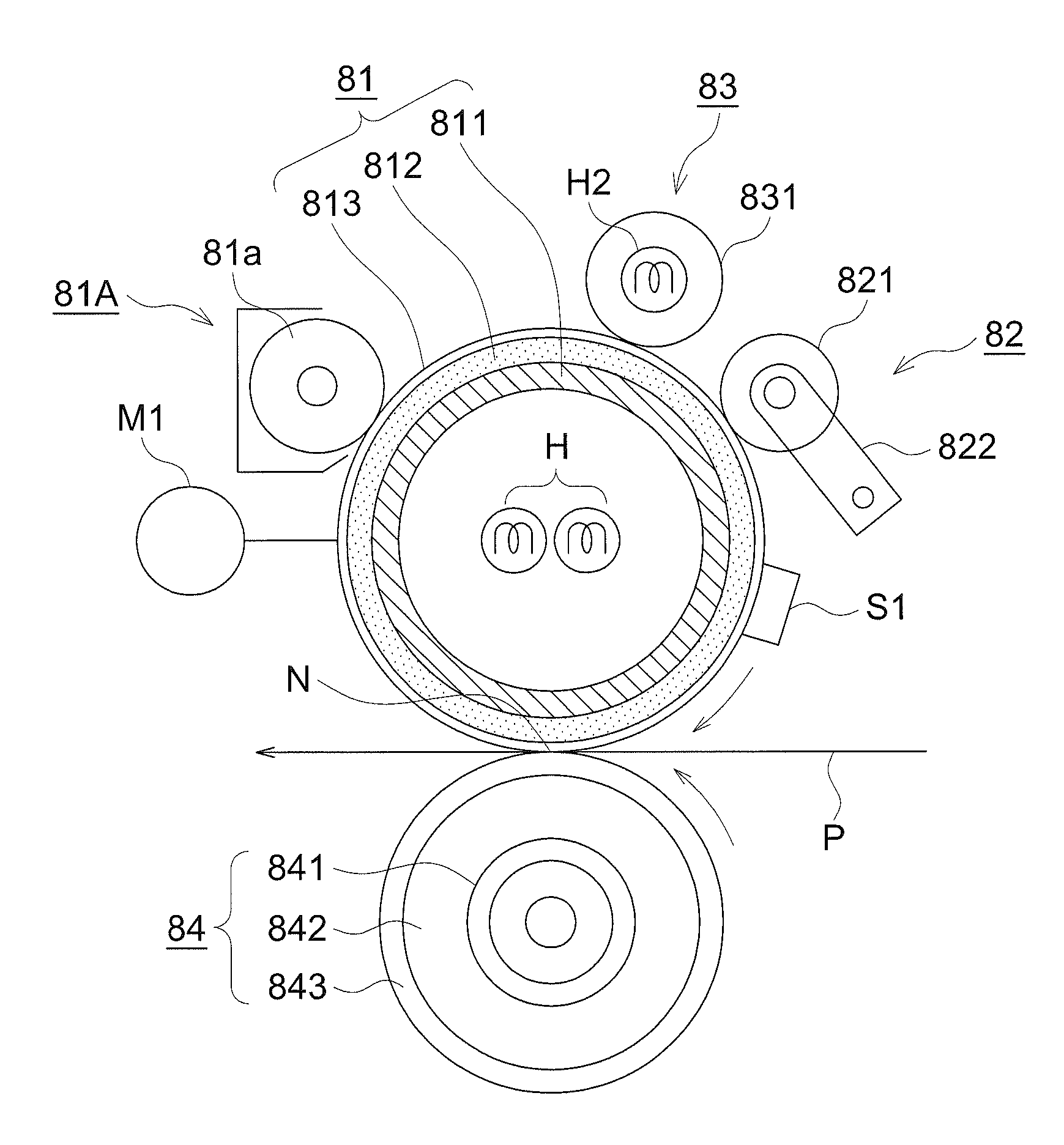
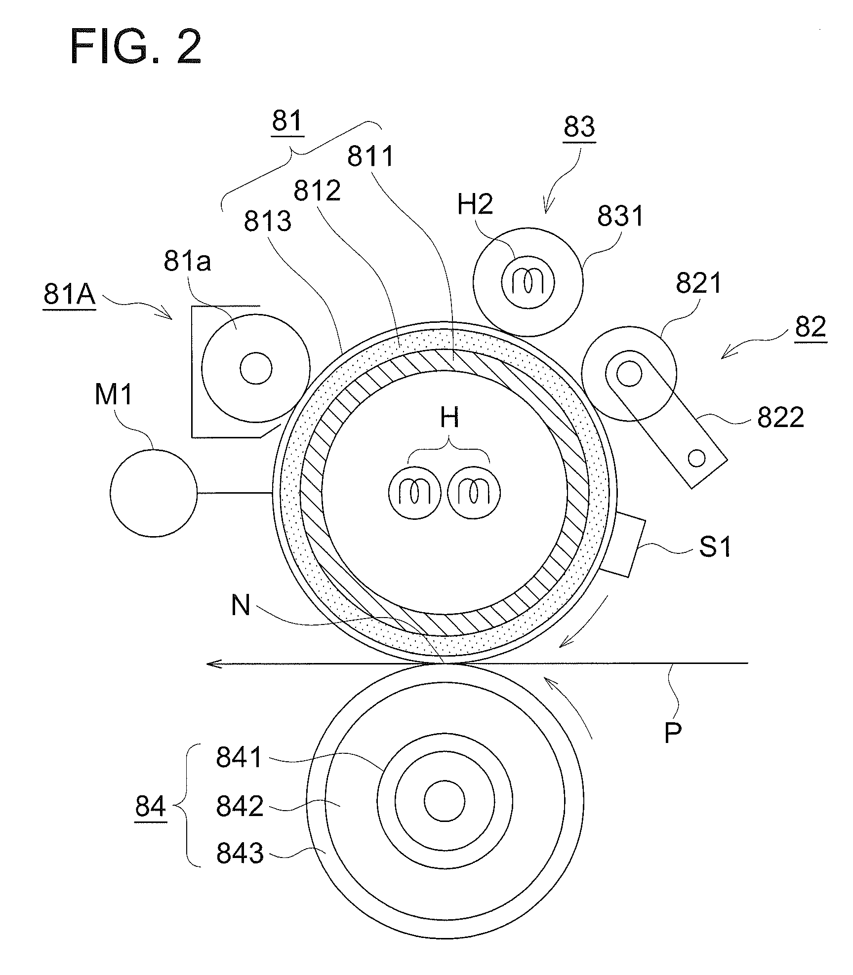
A fixing unit is provided with a fixing member to heat a recoding medium and to fix a toner image on the recording medium; a pressure member to press the fixing member to form a nip portion in which a recording medium carrying a toner image is nipped; an auxiliary heating member to heat the surface of the fixing member; and a surface recovery member, arranged at a downstream side of the first auxiliary heating member in a rotational direction of the fixing member, for recovering damage to a surface of the fixing member by making contact with and sliding on the fixing member.

Description

CROSS REFERENCE TO RELATED APPLICATION[0001]This application is based on Japanese Patent Application No. 2009-274265 filed with Japan Patent Office on Dec. 2, 2009, the entire content of which is hereby incorporated by reference.BACKGROUND OF THE INVENTION[0002]1. Field of the Invention[0003]The present invention relates to a fixing unit to fix a toner image on a recording medium by heating and pressing the recording medium, and an image forming apparatus provided with the fixing unit.[0004]2. Description of Related Art[0005]An image forming apparatus of an electrophotographic system such as a copier, a printer, and a facsimile machine, as well as a multifunction peripheral having such functions is available. In the fixing unit of this image forming apparatus, a heat roller system using a heat roller serving as a fixing member is widely used. For example, a fixing unit of this heat roller system is used in machines ranging from low-speed machines to high-speed machines and further f...

Claims


Application Information

Patent Timeline
Patent Type & Authority Patents(United States)
IPC IPC(8): G03G15/20
CPCG03G15/2035G03G15/2053
Inventor MARUKO, MASAMIOKUI, SUSUMU
Owner KONICA MINOLTA BUSINESS TECH INC
Learn More