Folding transport conveyor for a construction machine, automotive construction machine, as well as method for pivoting a transport conveyor

a technology for transporting conveyors and construction machines, which is applied in transportation and packaging, roads, highway maintenance, etc., can solve the problems of large space requirements, high apparatus-related effort, and large risk of piston-cylinder units being damaged in prior art, and achieves the effect of simplifying the design

Active Publication Date: 2013-04-23
WIRTGEN GMBH
View PDF27 Cites 69 Cited by
  • Summary
  • Abstract
  • Description
  • Claims
  • Application Information

AI Technical Summary

Benefits of technology

[0015]In addition, the cam mechanism enables detent positions to be provided in the limit positions by way of a corresponding curvature, so that the pivotable transport conveyor section can be retained in the limit positions in a self-locking fashion without requiring additional locking means.
[0021]It is of particular advantage in this design that the drive unit can be attached to the transport conveyor section articulated at the construction machine, while the cam mechanism is arranged at the pivotable transport section in a permanent fashion. As a result, it is not necessary to transfer feed lines for the driving device to the pivotable transport conveyor section.
[0029]Two pivoting mechanisms arranged in pairs and operated synchronously are preferably arranged at the sides next to the transport conveyor sections. In a preferred embodiment, parts of the pivoting mechanism corresponding to one another may be connected to one another by means of bridging elements in order to improve the synchronous operation and / or to create a stiffening effect. To this end, the part pairs of the pivoting mechanisms on both sides, arranged in pairs next to one another, may be connected to one another by cross struts. In addition, the support rollers forming the coupling element may be provided with a common axle and can thus also reinforce the structure of the cam mechanism.

Problems solved by technology

Construction machines that are provided with a transport conveyor, and in which the transport conveyor is articulated at the construction machine, can have a large space requirement in case of transport.
The prior art has the disadvantage of requiring a high apparatus-related effort as the pivotable transport conveyor section is not secured in its limit positions by the pivoting mechanism, and therefore requires locking devices in the limit positions.
In addition, a disadvantage is created by the fact that hydraulic feed lines to the pivotable transport conveyor section need to be provided which can easily be damaged when pivoting the folding transport conveyor into the transport position.
The disadvantage created by this prior art is that the piston-cylinder unit coupled to the pivotable transport conveyor section is fastened at the underside of said transport conveyor section, which poses a great risk of the piston-cylinder unit being damaged as it is arranged underneath the transport conveyor in an exposed fashion.
This design creates the disadvantage, however, that no mountings like, for instance, a suction system may be provided on the first transport conveyor section.
In addition, the conveyor belt needs to be slackened when pivoting the trans-port conveyor into the transport position because the pivot point is then too far away from the continuously revolving transport belt.

Method used


Image

  • Folding transport conveyor for a construction machine, automotive construction machine, as well as method for pivoting a transport conveyor
  • Folding transport conveyor for a construction machine, automotive construction machine, as well as method for pivoting a transport conveyor
  • Folding transport conveyor for a construction machine, automotive construction machine, as well as method for pivoting a transport conveyor

Examples


Embodiment Construction

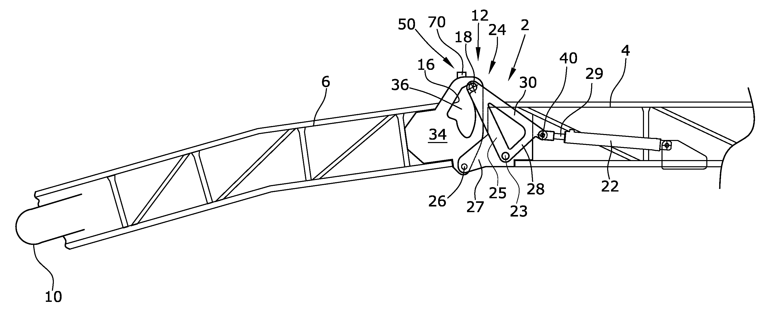
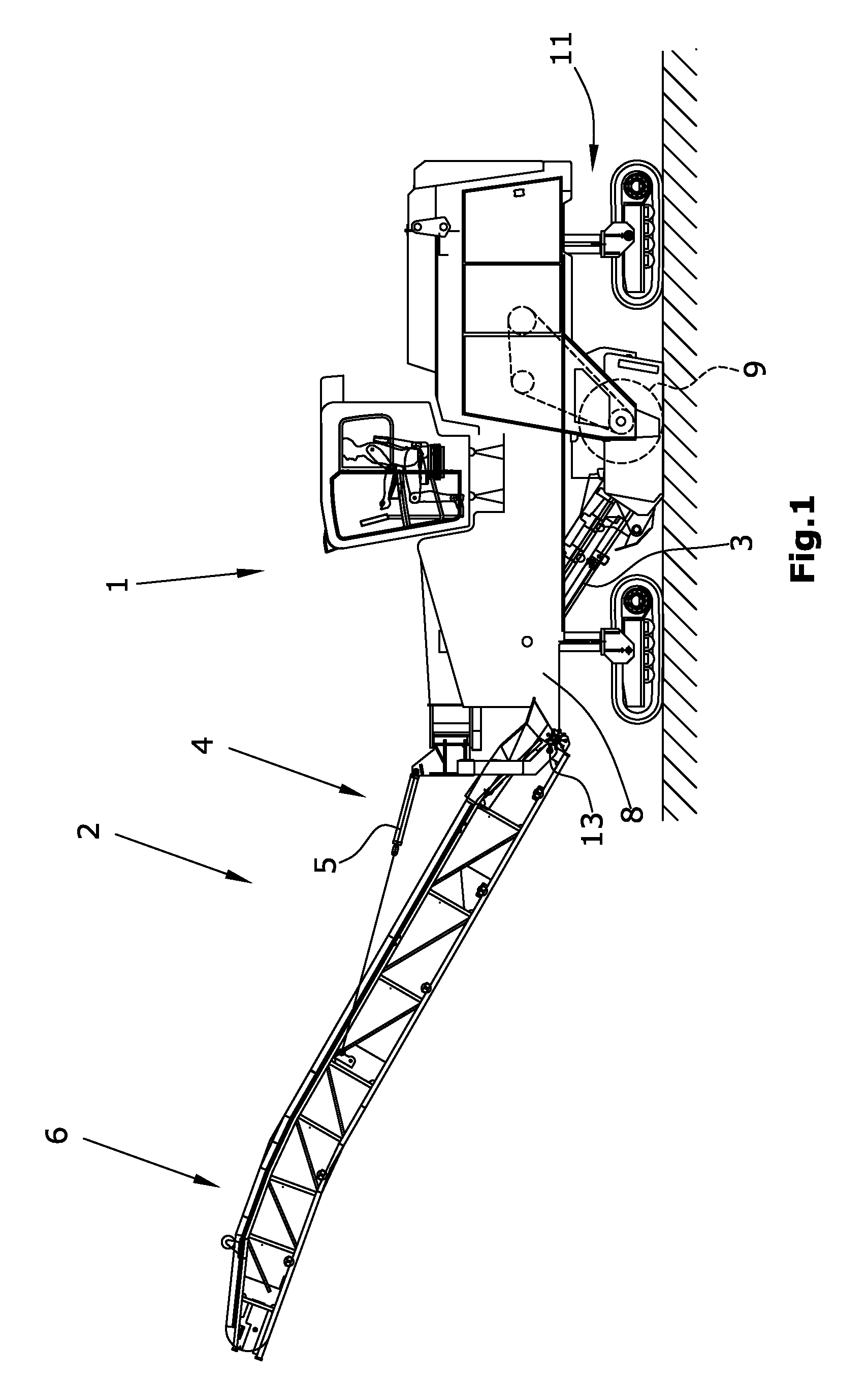
[0041]FIG. 1 shows a road milling machine for milling ground surfaces or traffic surfaces in the embodiment of a front-loading road milling machine. The road milling machine 1 comprises a chassis 11 with, for example, four crawler track units, which carries the machine frame 8 of the road milling machine 1. It is understood that the crawler track units may be substituted wholly or in part by wheel units. A milling drum 9, which extends transversely to the direction of travel, is mounted in the machine frame 8. The milling depth is preferably set by means of the height adjustment of the crawler track units via lifting columns. The road milling machine 1 depicted in FIG. 1 is also called a front-loading road milling machine as it is capable of conveying the milled material towards the front when seen in the direction of travel onto a transport vehicle. A first transport device, consisting of a transport conveyor 3, is arranged in front of the milling drum 9 when seen in the direction ...


PUM


Abstract

In a folding transport conveyor (2) for a construction machine (1), with a first transport conveyor section (4) articulated at the construction machine (1), a second transport conveyor section (6) articulated at the first transport conveyor section (4) in a pivoting fashion, with a conveyor belt (10) continuously revolving around both transport conveyor sections (6), and with at least one pivoting mechanism acting between the transport conveyor sections (4, 6), it is provided that the pivoting mechanism includes a cam mechanism (12).

Description

BACKGROUND OF THE INVENTION[0001]1. Field of the Invention[0002]The invention relates to a folding transport conveyor for a construction machine, an automotive construction machine, as well as a method for pivoting a transport section at the end of a folding transport conveyor.[0003]2. Description of the Prior Art[0004]Construction machines that are provided with a transport conveyor, and in which the transport conveyor is articulated at the construction machine, can have a large space requirement in case of transport.[0005]In order to not have to entirely remove the transport conveyor from the construction machine, it is already known to provide a folding transport conveyor which comprises a first transport conveyor section articulated at the construction machine, and a second pivotable transport conveyor section following the same. Transport conveyors of smaller size are pivoted manually. With larger transport conveyors, pivoting of the transport conveyor from a working position i...

Claims


Application Information

Patent Timeline
Patent Type & Authority Patents(United States)
IPC IPC(8): B65G15/26
CPCE01C23/088B65G21/14E01C19/30E01C19/42E01C23/12
Inventor BERNING, CHRISTIANKOETTING, HEINZSCHNEIDER, BJOERNLEY, HERBERTBERGES, JOERGLENZ, MARTIN
Owner WIRTGEN GMBH
Why Eureka
Try Eureka