Track container

a technology for forming cans and tracks, applied in the field of aircraft wing assemblies, can solve the problems of difficult to form cans in lighter materials such as carbon-fiber composites, complex and expensive processes, and a weight penalty

Inactive Publication Date: 2013-04-23
AIRBUS OPERATIONS LTD
View PDF8 Cites 10 Cited by
  • Summary
  • Abstract
  • Description
  • Claims
  • Application Information

AI Technical Summary

Problems solved by technology

Firstly, metal is relatively dense and thus incurs a weight penalty. However it is difficult to form the can in a lighter material such as carbon-fiber composite due to its complex curved shape.
Secondly, the can must be superplastically formed, or manufactured from welded sections of metal sheet. These are complex and expensive processes.
Thirdly, it can be difficult to accurately produce a complex shape, and as a result the volume of the can may be higher than necessary, reducing the volume of the fuel tank.
Fourthly, metal is susceptible to galvanic corrosion, and requires surface treatment.
Fifthly, Titanium, which is typically used to form the slat track can, is an expensive material.

Method used


Image

  • Track container
  • Track container
  • Track container

Examples


Embodiment Construction

)

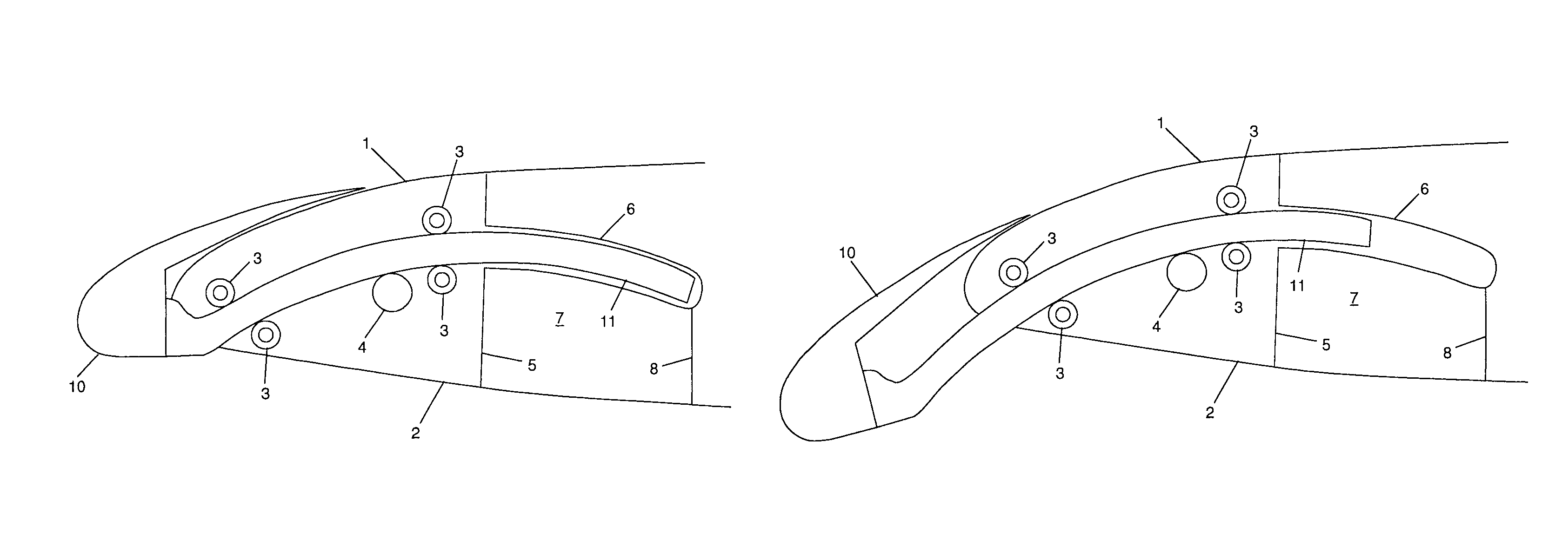
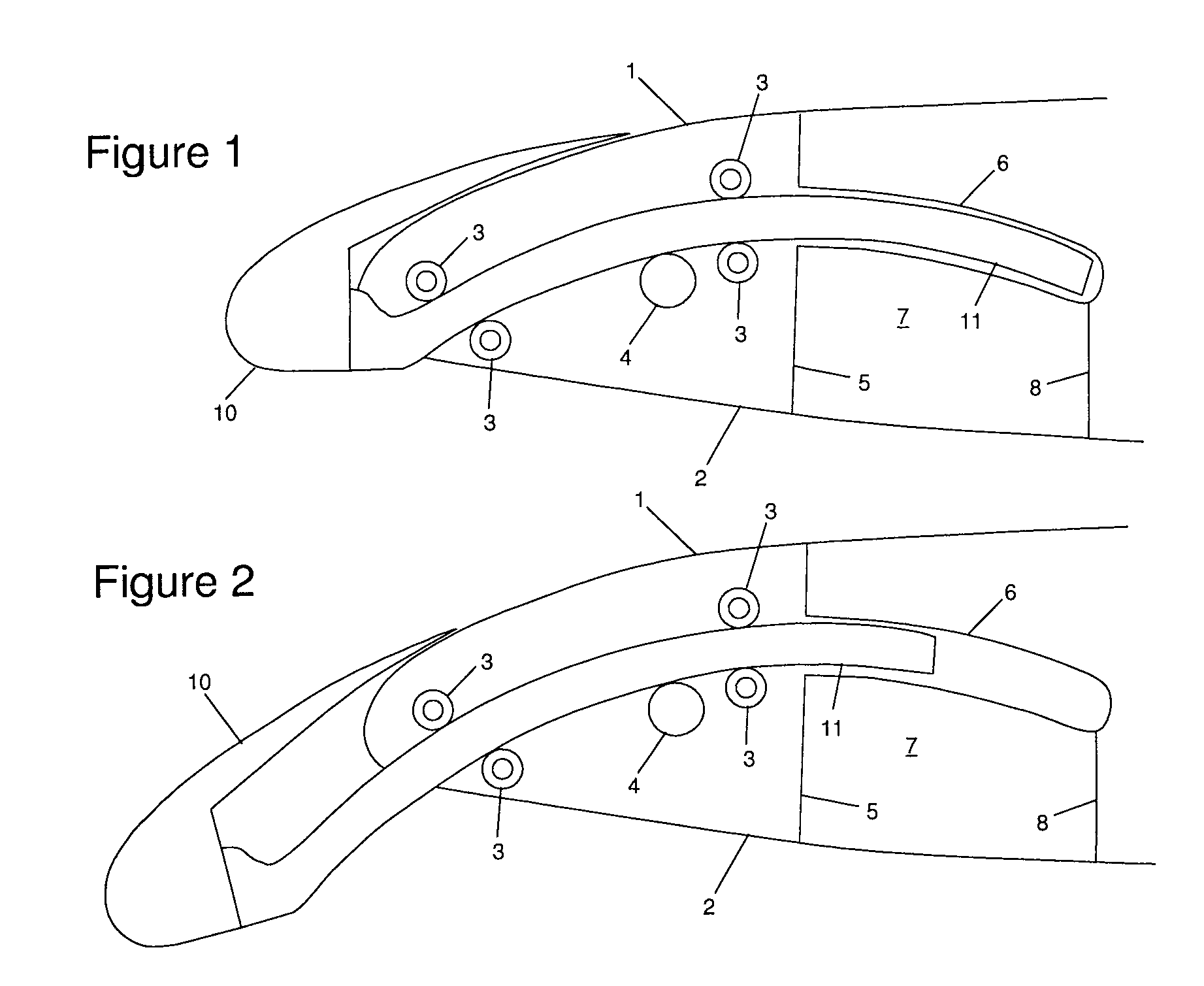
[0025]The leading edge of an aircraft wing assembly is shown in FIGS. 1 and 2. The wing has an upper surface; a lower surface 2 and a front spar 5 extending between them. A fuel tank 7 is located behind the front spar. A slat track container 6 is attached to the front spar and extends to the rear into the fuel tank 7. Any fluid which collects in the slat track container 6 can flow out via a drain pipe 8. Optionally the slat track container 6 may have a profiled internal surface which aids the removal of fluid by guiding it towards the drain pipe 8. A slat track 11 carrying a slat 10 extends through a hole in the front spar 5 and into the slat track container 6.

[0026]The slat track 11 follows a curved path which in the case of FIGS. 1 and 2 is approximately circular, although it more typically has a more complex curved shape. The slat track can be driven by a pinion gear 4 along a curved path defined by a set of rollers 3 between the retracted cruise position of FIG. 1 to an interme...


PUM

PropertyMeasurementUnit
conductiveaaaaaaaaaa
elastomericaaaaaaaaaa
shapeaaaaaaaaaa

Abstract

An aircraft wing assembly comprising: a spar; a fuel tank; a track container which is attached to the spar and extends into the fuel tank; a track which extends through the spar and into the track container; and a high-lift device, such as a slat or flap, carried by the track. The track container comprises a stiffening element encased in an elastomeric sheath. The track container is manufactured by placing a stiffening element and elastomeric material together in a mould; and compressing and heating them to cure and shape the elastomeric material.

Description

RELATED APPLICATIONS[0001]The present application is based on, and claims priority from, British Application Number GB0906074.0, filed Apr. 8, 2009, the disclosure of which is hereby incorporated by reference herein in its entirety.FIELD OF THE INVENTION[0002]The present invention relates to an aircraft wing assembly comprising: a spar; a fuel tank; a track container which is attached to the spar and extends into the fuel tank; a track which extends through the spar and into the track container; and a high-lift device, such as a slat or flap, carried by the track. The invention also relates to a track container for use in such an assembly, and a method of manufacturing a track container.BACKGROUND OF THE INVENTION[0003]Such track containers are conventionally made of metal and are known as “track cans”. Forming the track can from metal results in a number of problems.[0004]Firstly, metal is relatively dense and thus incurs a weight penalty. However it is difficult to form the can in...

Claims


Application Information

Patent Timeline
Patent Type & Authority Patents(United States)
IPC IPC(8): B64C9/14
CPCB29C43/12B29C43/3642B64C3/34B64C9/02B29C2043/3649B29K2105/0854B29L2031/3085B29L2031/712B29L2031/7172Y02T50/44Y02T50/40
Inventor SUTTON, DAVID ALISTAIRWEST, COLIN JOHN
Owner AIRBUS OPERATIONS LTD
Why Eureka
Try Eureka