Luminous flux control member and optical apparatus having the same

a technology of optical apparatus and control member, which is applied in the direction of optical elements, lighting and heating apparatus, instruments, etc., can solve the problem of inability to obtain satisfactory optical characteristics, and achieve the effects of reducing manufacturing costs, improving manufacturing efficiency, and simplifying the structure of metal molds

Active Publication Date: 2013-04-23
ENPLAS CORP
View PDF6 Cites 0 Cited by
  • Summary
  • Abstract
  • Description
  • Claims
  • Application Information

AI Technical Summary

Benefits of technology

[0015]According to the present invention, when light is totally reflected by the second inclined surface, light is emitted in a direction where an intensity gradient of light is alleviated from the extreme end section side to the base end section side of the second inclined surface. This is not influenced by whether or not an axis offset occurs. Accordingly, even if an axis offset occurs, it can be suppressed that a light distribution of light emitted from an emission area (that is, light from a luminous flux control member) is significantly offset from a designed light distribution. According to the present invention, since the suppression of the offset of light distribution due to the axis offset can be realized by the surface shape of the second inclined surface in place of the number of projecting sections, it is not necessary to form many fine projecting sections to a metal mold for molding the luminous flux control member and thus a metal mold structure can be simplified. Further, according to the present invention, since a total reflection surface having a sufficient size can be used by reducing the number of the projecting sections, a sufficient amount of light can be obtained in the second inclined surface. As a result, optical performance can be stabilized, manufacturing can be made easy, and the efficiency of use of light can be improved at the same time.

Problems solved by technology

In the case, since a light distribution of light emitted from the lens is significantly offset from a designed light distribution, a problem arises in that satisfactory optical characteristics cannot be obtained.

Method used


Image

  • Luminous flux control member and optical apparatus having the same
  • Luminous flux control member and optical apparatus having the same
  • Luminous flux control member and optical apparatus having the same

Examples


example

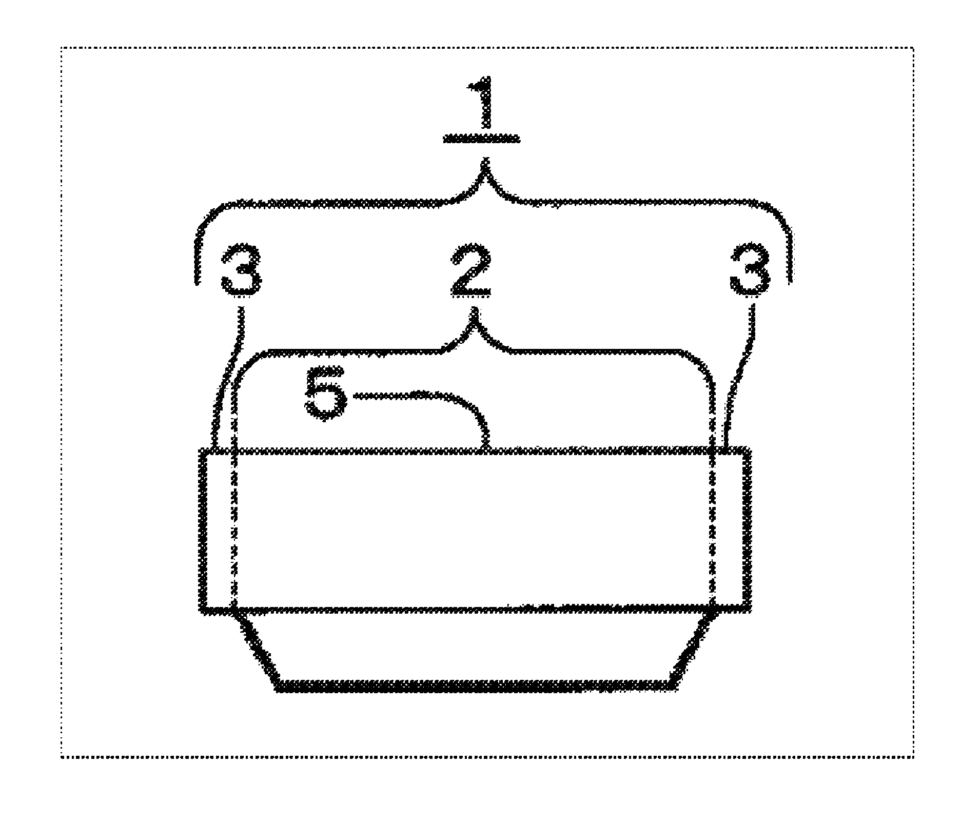
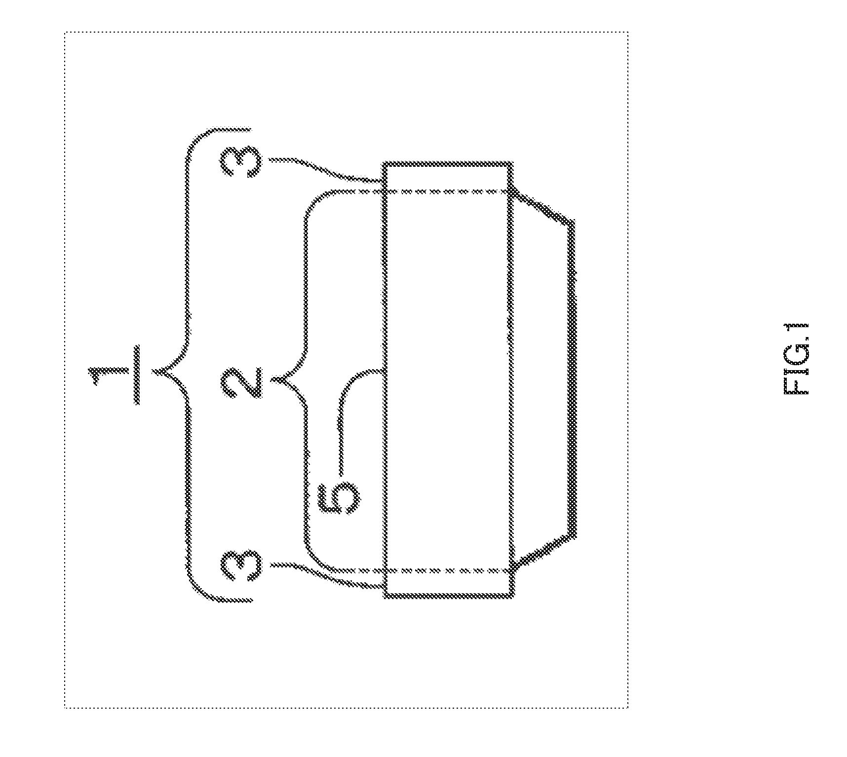
[0060]In the embodiment, as to luminous flux control member 1 having reflection surface 15 arranged as shown in FIG. 7, a light distribution when an axis offset did not occur between luminous flux control member 1 and an LED as light source 6, and a light distribution when an axis offset occurred were calculated by simulation. However, 0.1 mm (Y-axis direction) was set as an attachment error of the LED which could be actually assumed. Further, the amount of light reflected by reflection surface 15 of first projecting section 11 was set to 34% of the effective amount of light emitted from emission area 5 after the light was emitted from the LED and entered inside luminous flux control member 1.

[0061]A light distribution when an axis offset did not occur, that is, a designed light distribution was as shown in FIG. 8, and a light distribution when an axis offset occurred was as shown in FIG. 9.

[0062]Note that FIG. 8 and FIG. 9 show distributions of a ratio (%) of intensity of light emi...


PUM


Abstract

A luminous flux control member can stabilize an optical performance, make manufacturing easy and improve efficiency of use of light at the same time. A reflection surface (15) is formed in a surface shape, so that an extreme end section of the reflection surface (15) that is the most distant from an emission area (5) is positioned further inward in the radial direction than a base end section that is the closest to the emission area (5), and the reflection surface (15) intersects once a virtual surface that is inclined with respect to an optical axis connecting between the extreme end section and the base end section. The surface shape suppresses an offset of a light distribution of light emitted from the emission area (5) from a designed light distribution due to an offset between an optical axis and the center axis of light emitted from a light source.

Description

CROSS REFERENCE TO RELATED APPLICATIONS[0001]The disclosure of Japanese Patent Application No. 2010-137096, filed on Jun. 16, 2010, including the specification, drawings and abstract, is incorporated herein by reference in its entirety.TECHNICAL FIELD[0002]The present invention relates to a luminous flux control member and an optical apparatus having the luminous flux control member. In particular, the present invention relates to a luminous flux control member and an optical apparatus having the luminous flux control member preferable to illuminate light emitted from a light source to an illumination-target surface.BACKGROUND ART[0003]Conventionally, there is known a lens (so-called a Fresnel lens) having a lens surface that is divided to a plurality of concentric areas and formed in a saw blade shape (hereinafter called a Fresnel shape) as a lens suitable for reducing thickness and weight. This kind of lens is applied to a use in which a reduction of thickness is particularly adva...

Claims


Application Information

Patent Timeline
Patent Type & Authority Patents(United States)
IPC IPC(8): F21V13/04
CPCG02B19/0061G02B19/0028
Inventor SAITO, TOMOHIRO
Owner ENPLAS CORP
Why Eureka
Try Eureka