Multi-function auxiliary rudder system for jet propelled watercrafts

a jet propelled watercraft and auxiliary rudder technology, applied in the field of auxiliary systems, can solve problems such as the inability to function with articulating or biasing means

Active Publication Date: 2013-04-23
WALKOWIAK JEFFREY T
View PDF8 Cites 11 Cited by
  • Summary
  • Abstract
  • Description
  • Claims
  • Application Information

AI Technical Summary

Benefits of technology

[0010]The embodiments of the present invention described herein provide for the versatility of operating as a rudder assisted steering in power or reduced power mode, that is, slow or idle speeds, or the invention can be set to provide rudder assistance to the steering at all speeds. In either case, the rudders are capable of being deflected up if they contact a submerged object while the boat is moving or anchored.
[0020]In another embodiment, a set of variable effect rudders, using a fixed position side force stabilizer and several graduating mounting holes on the fins that allow the consumer to vary the amount of steering assistance they receive. From full assistance with the fins all the way down, they will get both high speed and slow speed assistance. With the fins part way down they get less assistance in high speed and with the fins all the way up, they only get low speed assistance. This system can use a number of positioning holes so they can fine tune the results they desire, without having to modify the system. In this variant of the invention, the auxiliary rudder system comprises a pair of spaced-apart fins, the fins being configured to be attached at one end to a proximal end of the nozzle drive system so that the fins are oriented along sides of the nozzle drive system. The fins extend in length from the proximal end of the nozzle drive system a predetermined distance beyond a jet water flow outlet of the nozzle drive assembly. A side force stabilizer member is configured to be fixed to an underside of the directional nozzle of the nozzle drive system. The stabilizer member is oriented transversely such that respective ends of the stabilizer member are attached to the inside surface of the fins. The fins are selectively attachable to the stabilizer member ends such that the fins are positioned in an “up” position, a “down” position and one or more intermediate positions relative to the stabilizer member.

Problems solved by technology

However, in normal operation, the articulating or bias means do not function due to the downward force of the jet pump.

Method used


Image

  • Multi-function auxiliary rudder system for jet propelled watercrafts
  • Multi-function auxiliary rudder system for jet propelled watercrafts
  • Multi-function auxiliary rudder system for jet propelled watercrafts

Examples


Embodiment Construction

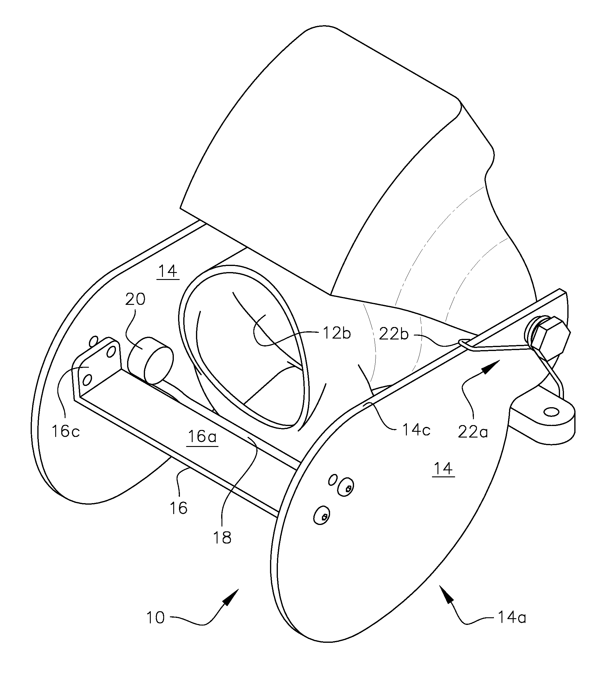
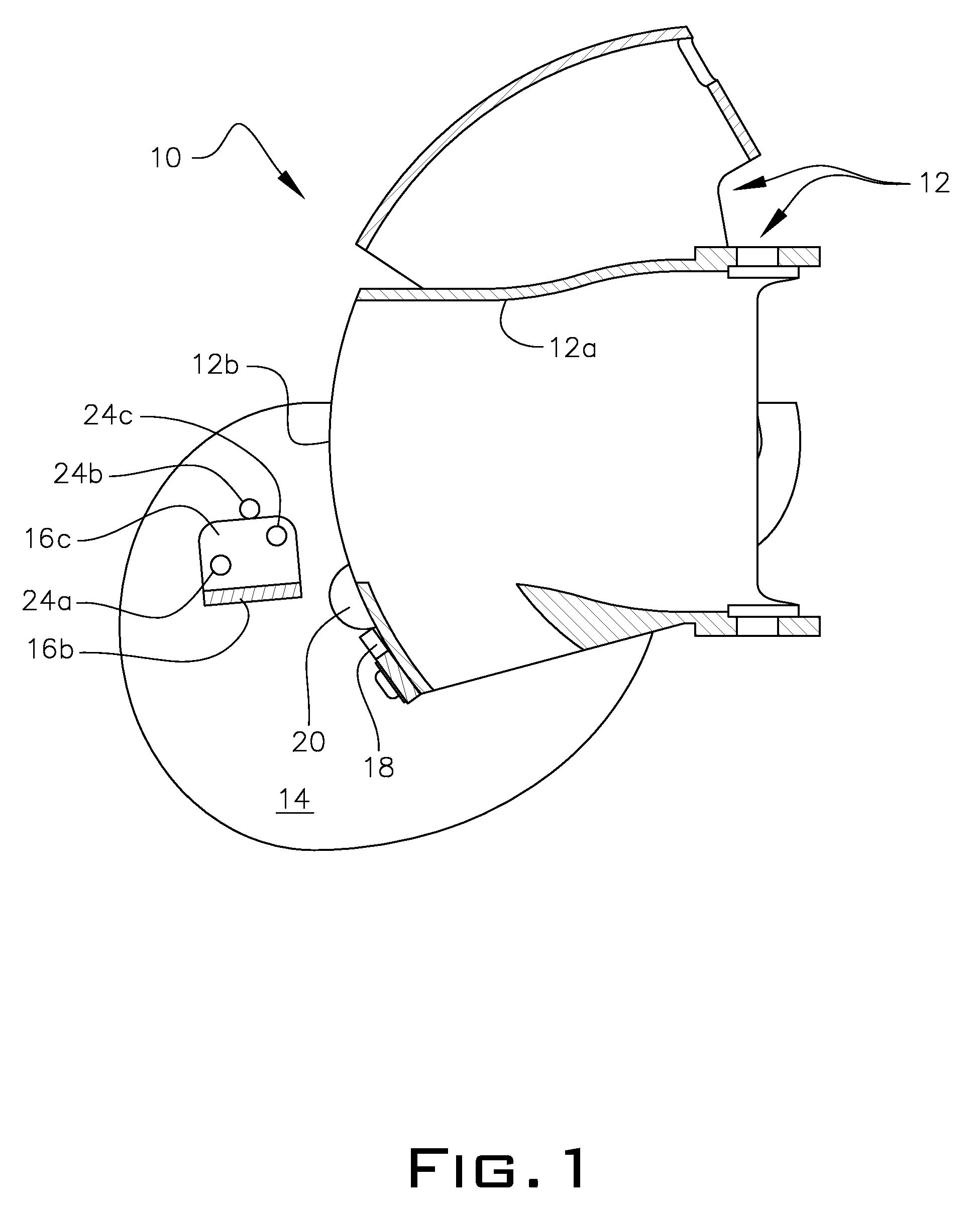
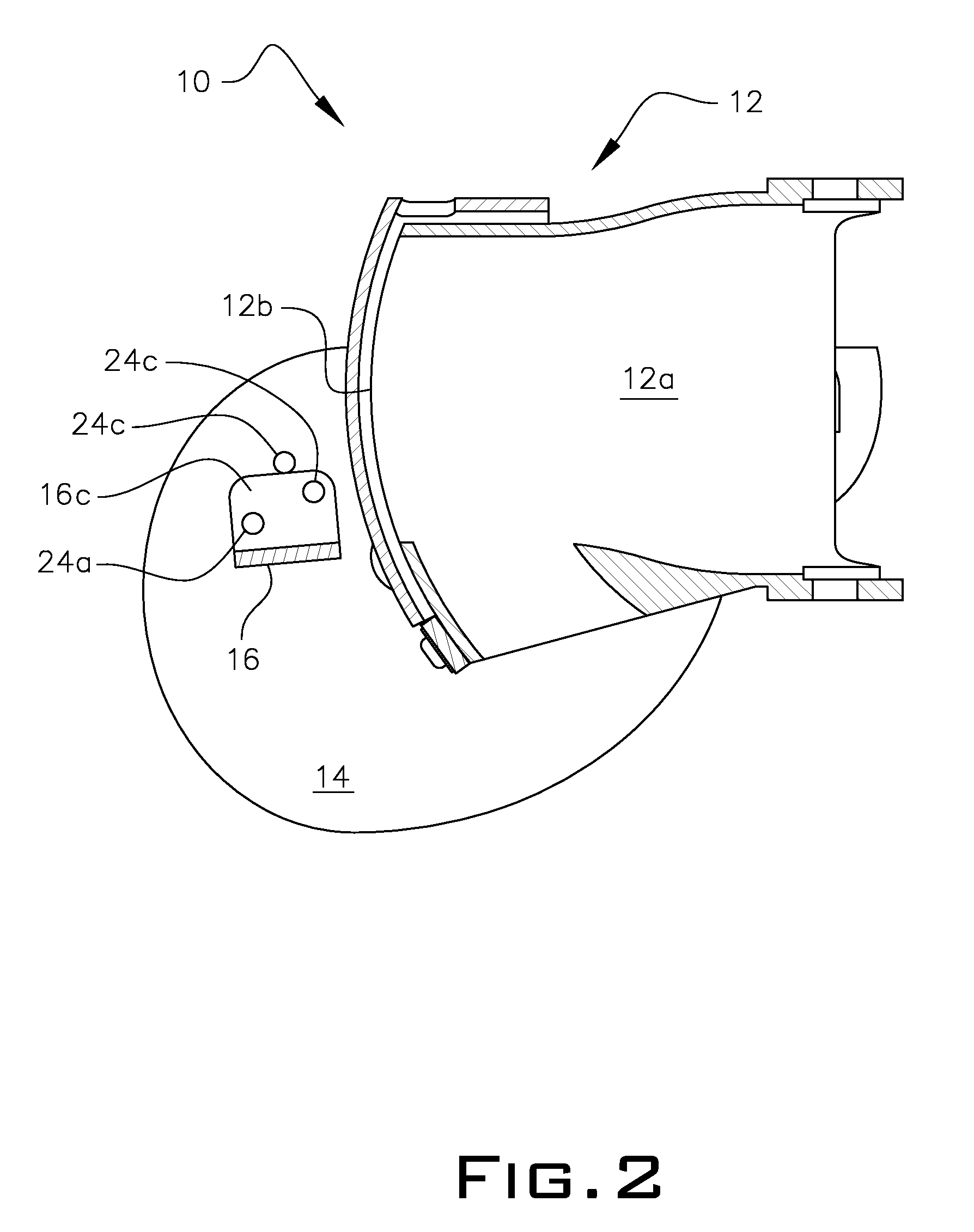
[0041]Referring now to the drawings, FIGS. 1-11 conceptually disclose the present invention, which is an auxiliary rudder system configured for use with a jet propelled watercraft having a directional nozzle drive system 12. The directional nozzle itself is depicted as 12a and its outlet is depicted as 12b. The rudder system is depicted generally as 10.

[0042]The auxiliary rudder system 10 comprises a pair of spaced-apart fins 14. The fins 14 are configured to be pivotally attached at one end to a proximal end of said nozzle drive system 12 so that said fins 14 pivot up or down along sides of said nozzle drive system 12. The fins 14 extend in length from said proximal end of said nozzle drive system 12 a predetermined distance beyond a jet water flow outlet 12b of the directional nozzle 12a of the drive assembly 12. The length beyond the outlet plane is sufficient to include the dual thrust actuator 16 between the fins 14 and to also subject the actuator surfaces 16a,16b to thrust fo...


PUM


Abstract

A rudder system that uses a dual purpose thrust operated actuator. The actuator is selectively positioned for use in an up or constant down mode. While in the up mode, the actuator uses the force of the jet pump to raise the rudders out of the water at speed, and with the actuator set in the down mode, the invention uses the force of the jet pump water to hold the rudder in the water. In an alternative embodiment, the invention includes anti-oscillating veins attached to the thrust operated actuator. In another alternative embodiment, the travel of the actuator is limited by configuring it to come into contact with a rudder stabilizer bar. Another embodiment includes providing adjustable fin positions relative to the side force stabilizer.

Description

RELATED APPLICATION[0001]This application is a continuation-in-part application of U.S. patent application Ser. No. 13 / 103,154 filed May 9, 2011.FIELD OF THE INVENTION[0002]The invention relates to an auxiliary system for providing positive steering to marine crafts using jet propulsion systems, typically personal jet driven watercrafts such as jet boats and jet skis.BACKGROUND OF THE INVENTION[0003]By way of background, there are two types of jet propulsion systems currently in use. The first type most commonly used is found on personal watercrafts usually referred to as Jet Skis. This type uses a directional nozzle. The nozzle turns from side to side directing water from the jet to change the direction of the watercraft.[0004]The second type is commonly used on Jet Boats and incorporates a movable hood or cover over the directional nozzle to force the water from the jet below the boat to add reverse thrust and allows the boat to back up. For forward thrust, it is pulled up above t...

Claims


Application Information

Patent Timeline
Patent Type & Authority Patents(United States)
IPC IPC(8): B63H11/117
CPCB63H25/46
Inventor WALKOWIAK, JEFFREY T.
Owner WALKOWIAK JEFFREY T
Why Eureka
Try Eureka