
Optical device with electrically variable extended depth of field

an optical device and depth of field technology, applied in the field of optical devices with electrically variable extended depth of field, can solve the problems of requiring a large, bulky and relatively expensive element, requiring iris to be large, and not practical in ultra-compact cameras such as cell phone cameras, and achieves the effect of sharp detail

Active Publication Date: 2014-04-01
OMNIVISION TECH INC
View PDF16 Cites 6 Cited by
  • Summary
  • Abstract
  • Description
  • Claims
  • Application Information

AI Technical Summary

Benefits of technology

The present optical device offers a camera with a longer depth of field and the ability to adjust the amount of depth of field to create sharp details in images. This allows for capturing pictures of landscapes or sports activities with the same level of detail.

Problems solved by technology

However, this range comes at the cost of a drop in modulation transfer function (MTF) at a given range of conjugates.
However, an iris requires a large, bulky and relatively expensive element that is practical only in large cameras, and is not practical in ultra-compact cameras, such as cell phone cameras.

Method used


Image

  • Optical device with electrically variable extended depth of field
  • Optical device with electrically variable extended depth of field
  • Optical device with electrically variable extended depth of field

Examples


Embodiment Construction

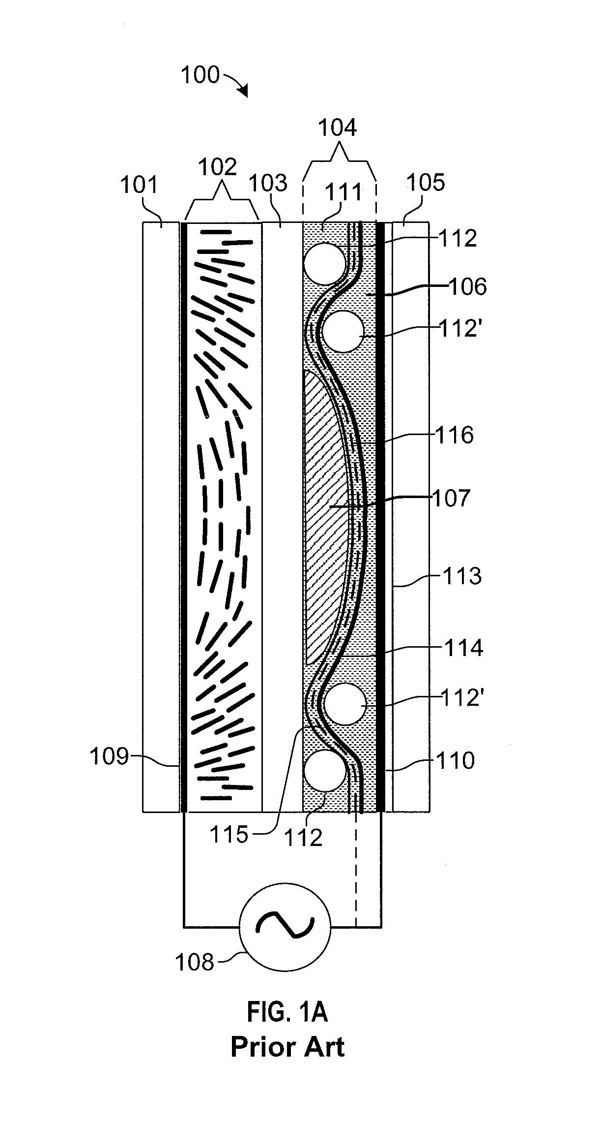
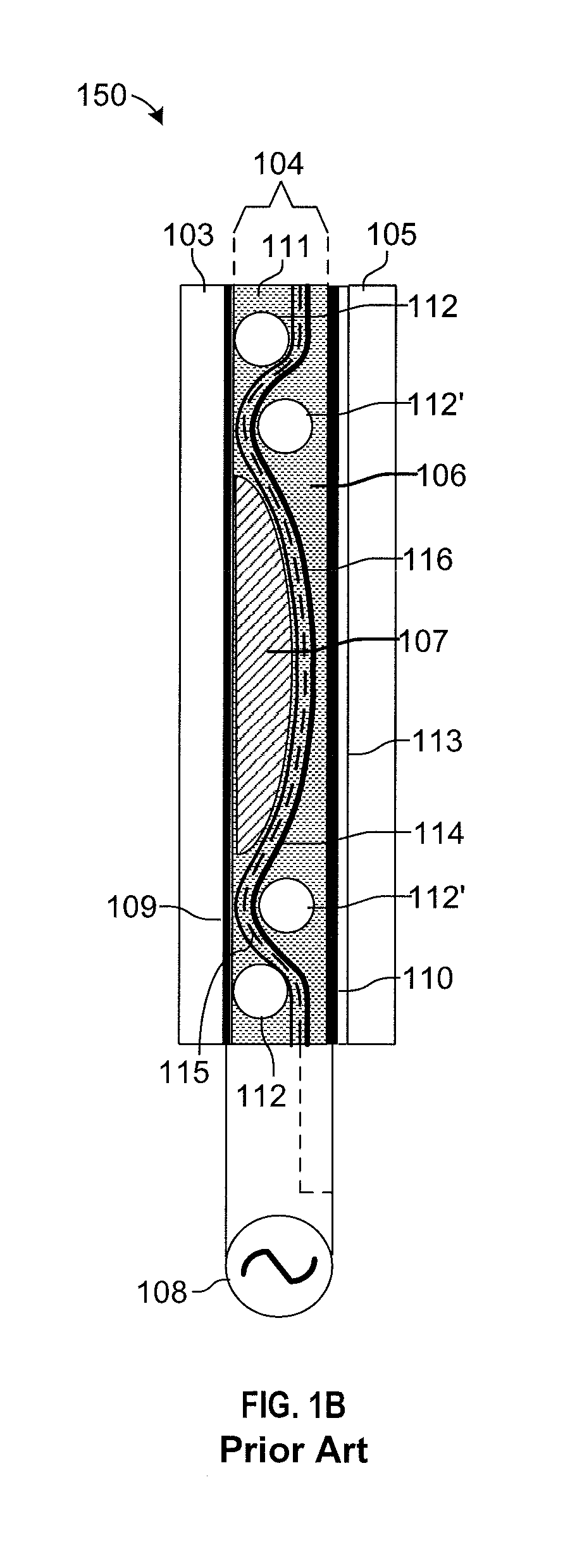
[0015]FIG. 1A is a diagram showing a prior art tunable liquid crystal lens 100. Lens 100 has a liquid crystal (LC) layer 102, and a ‘hidden’ layer 104 with a core lens 107. Layer 104 is optically transparent and induces an electric field in LC layer 102 that is shaped proportionally with respect to the shape of the core lens 107. Core lens 107 is fabricated from an optically transparent material. Focusing of lens 100 is performed by controlling the amplitude and / or the frequency of a signal applied to electrodes 109 / 110 via power source 108.

[0016]LC materials typically present polar molecules that are fairly mobile and, therefore, respond to the presence of an electric field by realigning their poles along the direction of the field. Also because of the polar nature of LC molecules, when they are poled (that is, their molecules are aligned along a preferred axis) they present refractive indices that are dependent on the polarization of light that is transmitted through them. When li...


PUM

PropertyMeasurementUnit
voltageaaaaaaaaaa
frequencyaaaaaaaaaa
dielectric constantsaaaaaaaaaa

Abstract

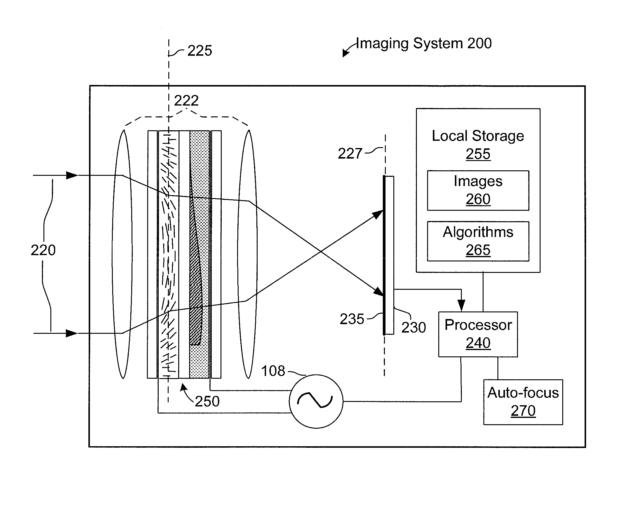
A system and method for providing an optical device with a variable extended depth-of-field (EDOF). The optical device includes an optically transparent liquid crystal layer, an optically transparent phase mask, optically aligned with the liquid crystal layer and separated therefrom by an optically transparent substrate, an optically transparent index-matching layer, disposed adjacent to one surface of the phase mask, and having a refractive index substantially matching that of the phase mask; and a pair of electrodes for generating an electric field acting on said liquid crystal layer to change the depth of field of the imaging system in proportion to the amplitude of a signal applied to the electrodes.

Description

BACKGROUND[0001]Extended depth-of-field (EDOF) provides camera users with an increased range over which objects are in focus. However, this range comes at the cost of a drop in modulation transfer function (MTF) at a given range of conjugates. The traditional method of solving this problem is by providing cameras with an aperture stop with controllable diameter, such as an iris. However, an iris requires a large, bulky and relatively expensive element that is practical only in large cameras, and is not practical in ultra-compact cameras, such as cell phone cameras. Also, an iris achieves an increased depth of field by effectively increasing the lens focal ratio, with a corresponding result of reducing the amount of light reaching the lens and camera sensor by an amount proportional to the reduction in the area of the aperture. Thus, there is a need for systems and methods capable of providing camera users with variable amounts of EDOF with enough flexibility to adapt to different im...

Claims


Application Information

Patent Timeline
Patent Type & Authority Patents(United States)
IPC IPC(8): G02F1/133H04N5/225
CPCG02F1/133371G02F1/29G02B27/0075G02F2001/294G02F1/294
Inventor SILVEIRA, PAULO, E., X.
Owner OMNIVISION TECH INC
Learn More