Apparatus comprising a compact telescope

a compact telescope and telescope technology, applied in the field of imaging optics, can solve the problems of large field of view, large off-axis aberrations that must be corrected, and require low-profile optics, so as to facilitate computational stitching a single composite image, reduce the profile or thickness of the optics, and increase the field of view

Active Publication Date: 2015-06-25
DUKE UNIV
View PDF8 Cites 13 Cited by
  • Summary
  • Abstract
  • Description
  • Claims
  • Application Information

AI Technical Summary

Benefits of technology

[0009]In accordance with an illustrative embodiment of the invention, an array of compact catadioptric (refractive and reflective) optics is used to provide a camera for a mobile device (e.g., smartphone, etc.). The present inventors recognized that a catadioptric design is well suited for such service because the beam path through such optics is “folded,” thereby enabling a reduced profile or thickness for the optics. In the illustrative embodiment, the catadioptric optics are implemented as an array of Schmidt-Cassegrain telescopes, which, as a consequence of the two reflections that occur in each telescope, enable an optical path or train that is up to three times longer than the physical thickness of the telescope.
[0010]Each compact telescope in the array can have a relatively moderate field-of-view (c.a., 25 degrees). To increase the field-of-view, the axis of each of the telescopes in the array is tilted with respect to that of other telescopes and oriented so that neighboring micro-ca

Problems solved by technology

That is, very low profile optics are required.
These requirements are, unfortunately, at odds with one a

Method used


Image

  • Apparatus comprising a compact telescope
  • Apparatus comprising a compact telescope
  • Apparatus comprising a compact telescope

Examples


example

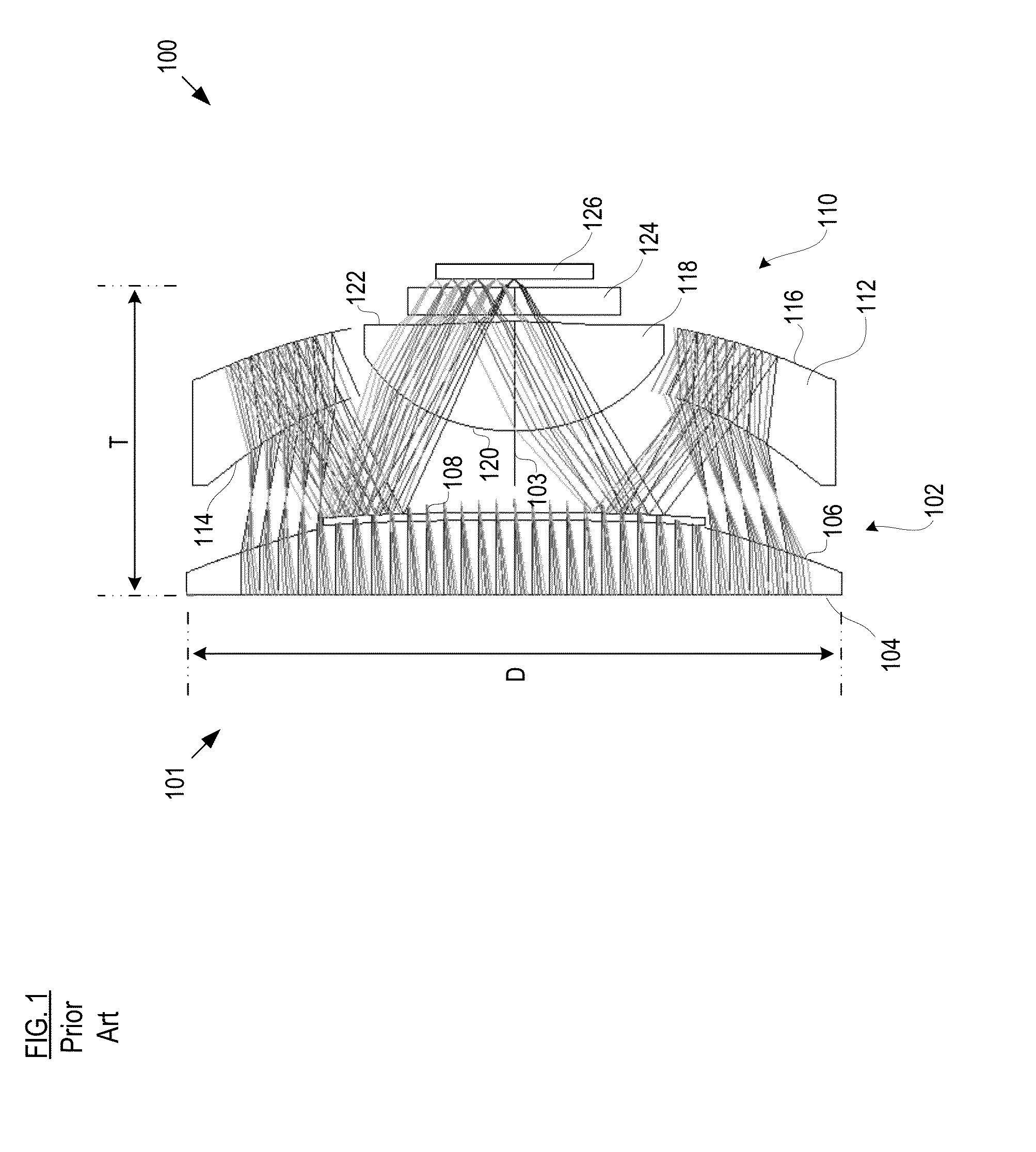
[0057]In an example design of catadioptric telescope 101, diameter D, of front optical element 102 (and hence telescope 101) is 9.2 mm and thickness T of telescope 100 is 4.5 mm. The entrance pupil of telescope 101 is 8 mm and the focal length is 5 mm. Telescope 101 images from −12.5 to 12.5 degrees off-axis, with design wavelengths in the range of 486 to 656 nanometers (nm).

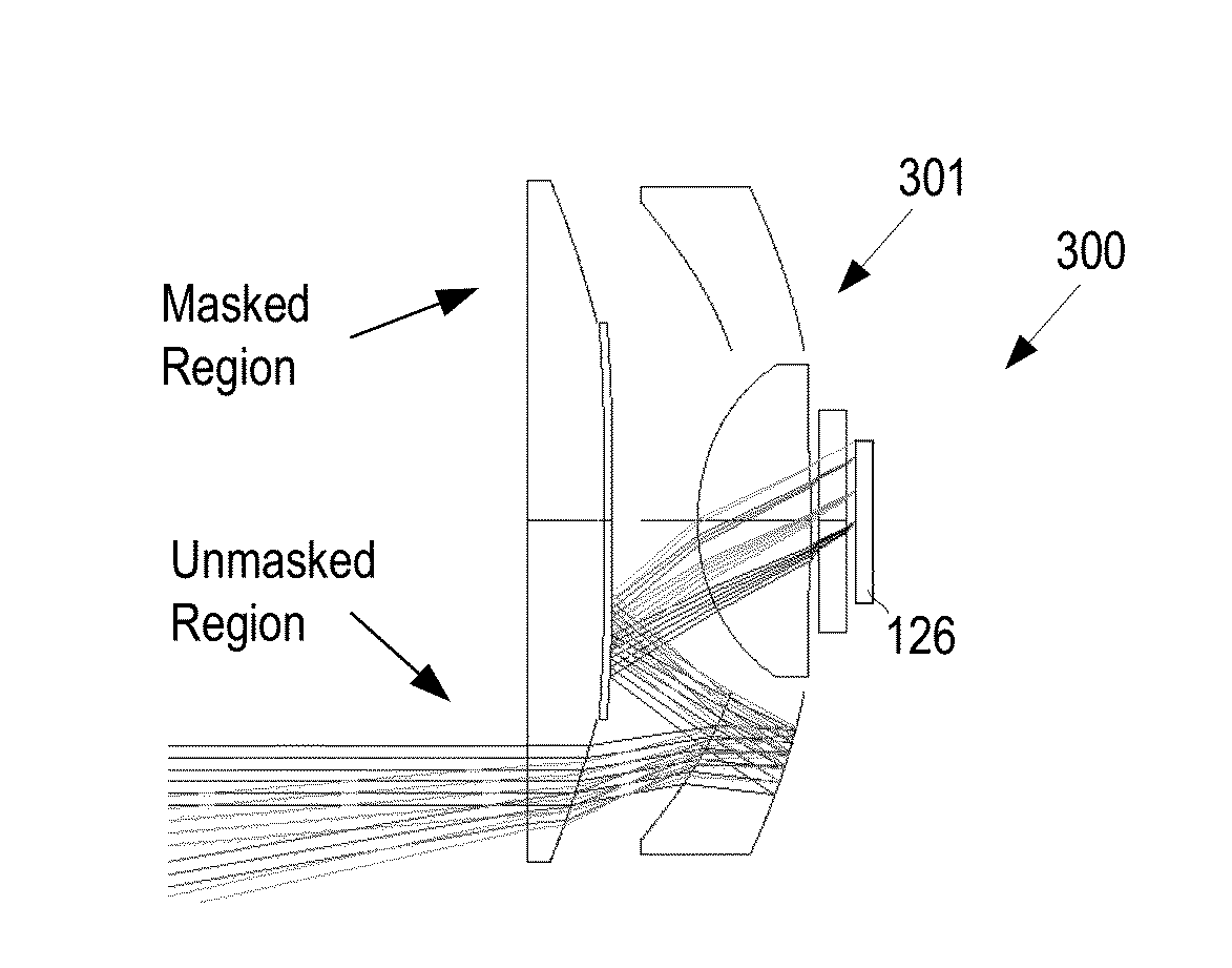
[0058]Field flattener 118 removes astigmatism and field curvature, so that the example design achieves an f / # of 0.6. The effective f / # for illumination varies from 1.0 at the center to 1.2 at the edge thereof. As a consequence, this design of telescope 101 can operate sufficiently in conditions of low-light where most mobile-phone cameras operate poorly.

[0059]The image field is 2.2 mm in diameter; it is designed for a 0.001 mm pixel CMOS sensor (an implementation of focal plane array 126). This is consistent with the recent generation of CMOS backside-illuminated sensors. The instantaneous field-of-view is 40 a...


PUM


Abstract

A camera system for a mobile device includes an array of compact catadioptric telescopes wherein at least some of the telescopes have a portion of their aperture truncated. At least some of the catadioptric telescopes in the array are tilted with respect to the system optical axis.

Description

CROSS REFERENCE TO RELATED APPLICATIONS[0001]This case priority of U.S. Pat. Appl. 61 / 918,788, which was filed Dec. 20, 2013 and is incorporated herein by reference. This case is related to U.S. patent application Ser. No. 14 / 068,708, filed Oct. 31, 2013, which is incorporated herein by reference.STATEMENT REGARDING FEDERALLY-SPONSORED RESEARCH[0002]This invention was made with Government support under grant number NBCHC090032 awarded by the Defense Advanced Research Projects Agency (DARPA). The Government has certain rights in the invention.FIELD OF THE INVENTION[0003]The present invention relates to imaging optics in general, and, more particularly, to camera optics for use in cell phones.BACKGROUND OF THE INVENTION[0004]Over the past decade, integration of cameras with mobile devices has become increasingly common. The desired thickness for tablets and cell phones is typically less than 1 centimeter (cm) and as thin as about 5 millimeters (mm). Since the ideal camera integrated i...

Claims


Application Information

Patent Timeline
IPC IPC(8): G02B13/00G02B23/02G02B17/08
CPCG02B13/0065G02B23/02G02B17/0856G02B17/08G02B23/06G02B17/0808
Inventor MARKS, DANIELBRADY, DAVID JONESHAGEN, NATHAN ADRIAN
Owner DUKE UNIV
Why Eureka
Try Eureka