
Low-profile broadband patch antenna

A patch antenna and low-profile technology, applied in the field of mobile communications, can solve the problem of difficult increase of antenna bandwidth, achieve stable directional pattern, high-efficiency directional pattern, and simple production

Inactive Publication Date: 2018-03-13
NANJING UNIV OF POSTS & TELECOMM
View PDF3 Cites 2 Cited by
  • Summary
  • Abstract
  • Description
  • Claims
  • Application Information

AI Technical Summary

Problems solved by technology

[0004] The purpose of the present invention is to provide a low-profile broadband patch antenna, which aims to solve the problem that the antenna bandwidth is difficult to increase when the antenna height is limited in mobile communications

Method used


Image

  • Low-profile broadband patch antenna
  • Low-profile broadband patch antenna
  • Low-profile broadband patch antenna

Examples


Embodiment Construction

[0035] specific implementation plan

[0036] In order to make the object, technical solution and advantages of the present invention more clear, the present invention will be further described in detail below in conjunction with the examples. It should be understood that the specific embodiments described here are only used to explain the present invention, not to limit the present invention.

[0037] The structure of the present invention will be described in detail below in conjunction with the accompanying drawings.

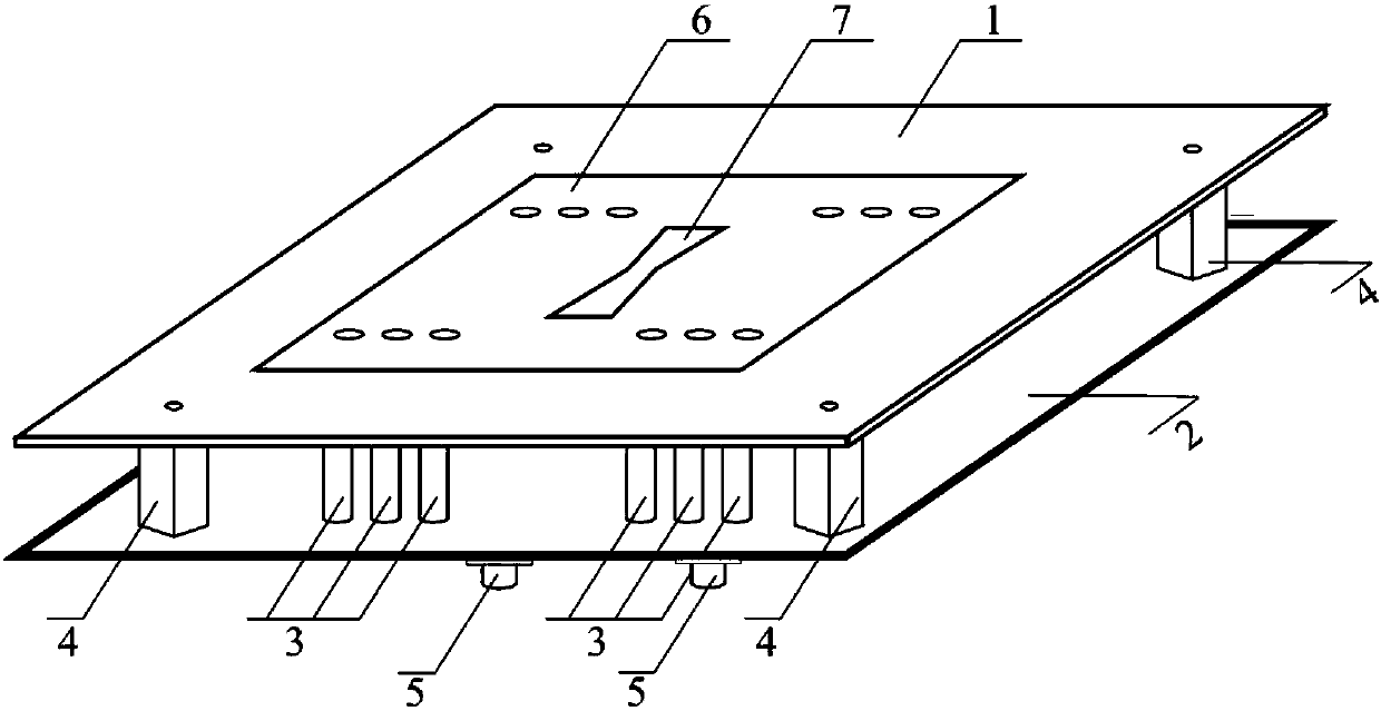
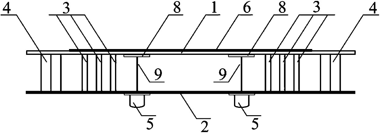
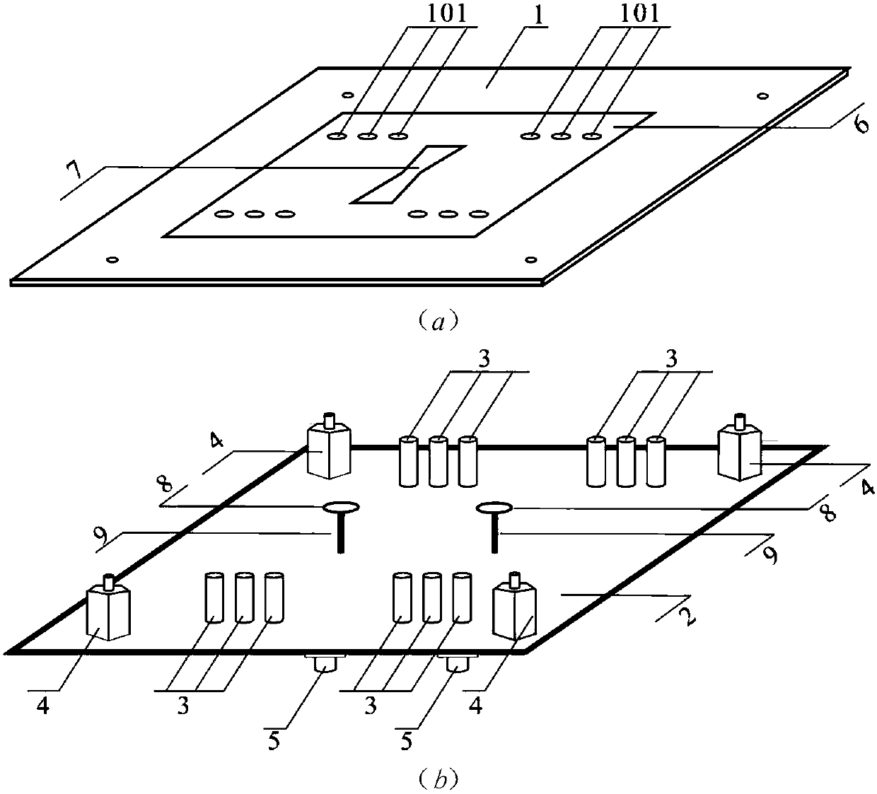
[0038] Please refer to Figure 1 ~ Figure 3 The low-profile broadband patch antenna of the embodiment of the present invention includes a dielectric substrate 1, a rectangular radiation element 6 located on one surface of the substrate, a pair of circular metal sheets 8 located on the other surface of the substrate, and a metal floor 2 located at a certain distance below the substrate , and twelve short-circuit components 3 connecting the rectangular radiati...


PUM


Abstract

The invention discloses a low-profile broadband patch antenna. The low-profile broadband patch antenna comprises a suspended dielectric substrate, a rectangular radiation element positioned on one surface of the dielectric substrate, a metal floor positioned below the dielectric substrate with a certain distance, and a plurality of short circuit parts which pass through the dielectric substrate tobe connected with the rectangular radiation element and the metal floor; a metal-free hexagonal groove is formed in the center of the rectangular radiation element; and the short circuit parts are symmetrical around the center line of the two groups of edges of the rectangular radiation element. The thickness of the patch antenna is only 0.06 freedom wavelengths, and the impedance bandwidth is 56% or above; and the antenna has the characteristics of simple structure, low profile, high frequency bandwidth, high efficiency, stable directional pattern and the like.

Description

technical field [0001] The invention belongs to the technical field of mobile communication, and in particular relates to a low-profile broadband patch antenna. Background technique [0002] Patch antennas are widely used in wireless communication systems due to their light weight, small size, and easy conformality. However, the impedance bandwidth of the traditional microstrip antenna is only about 10% when the section height is 0.06λ. With the continuous development of wireless communication systems, the working bandwidth of the antenna is a very important technical indicator. In order to meet the current needs of high-speed and large-capacity communications, it is a development trend for patch antennas to have low-profile and wide-band characteristics. At present, the bandwidth widening method of the microstrip antenna is mainly realized by increasing the thickness of the dielectric plate, adding parasitic elements, improving the feeding structure, and loading gaps on t...

Claims


Application Information

Patent Timeline
Patent Type & Authority Applications(China)
IPC IPC(8): H01Q1/38H01Q1/48H01Q1/50
CPCH01Q1/38H01Q1/48H01Q1/50
Inventor 祝雷刘能武李波汤一铭
Owner NANJING UNIV OF POSTS & TELECOMM
Learn More