High efficiency, high frequency amplifiers

a high-efficiency, amplifier technology, applied in the direction of amplifiers with semiconductor devices only, amplifiers with semiconductor devices/discharge tubes, amplifiers, etc., can solve the problem of small leakage current of fet, and achieve the effect of improving efficiency and synchronizing fets

Active Publication Date: 2013-04-23
AMCOM COMM
View PDF7 Cites 24 Cited by
  • Summary
  • Abstract
  • Description
  • Claims
  • Application Information

AI Technical Summary

Benefits of technology

[0003]According to the present invention, capacitors of specific values are connected in parallel with the drain and source terminals of each of the field-effect transistors (“FETs”) connected in series according to the '367 patent, except the first thereof. This results in improved synchronization of the FETs, which results in improved efficiency.

Problems solved by technology

Unfortunately each FET has a small leakage current due to the gate capacitance.

Method used


Image

  • High efficiency, high frequency amplifiers
  • High efficiency, high frequency amplifiers
  • High efficiency, high frequency amplifiers

Examples


Embodiment Construction

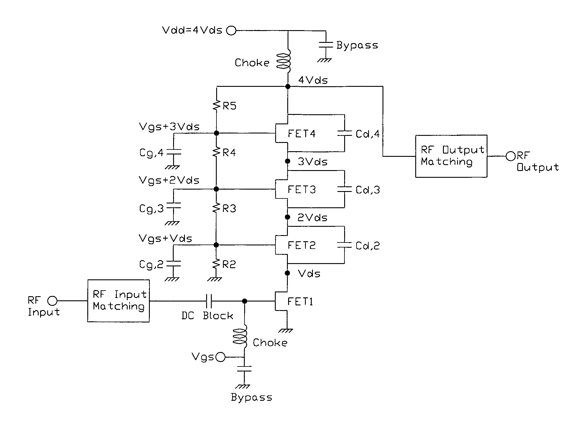
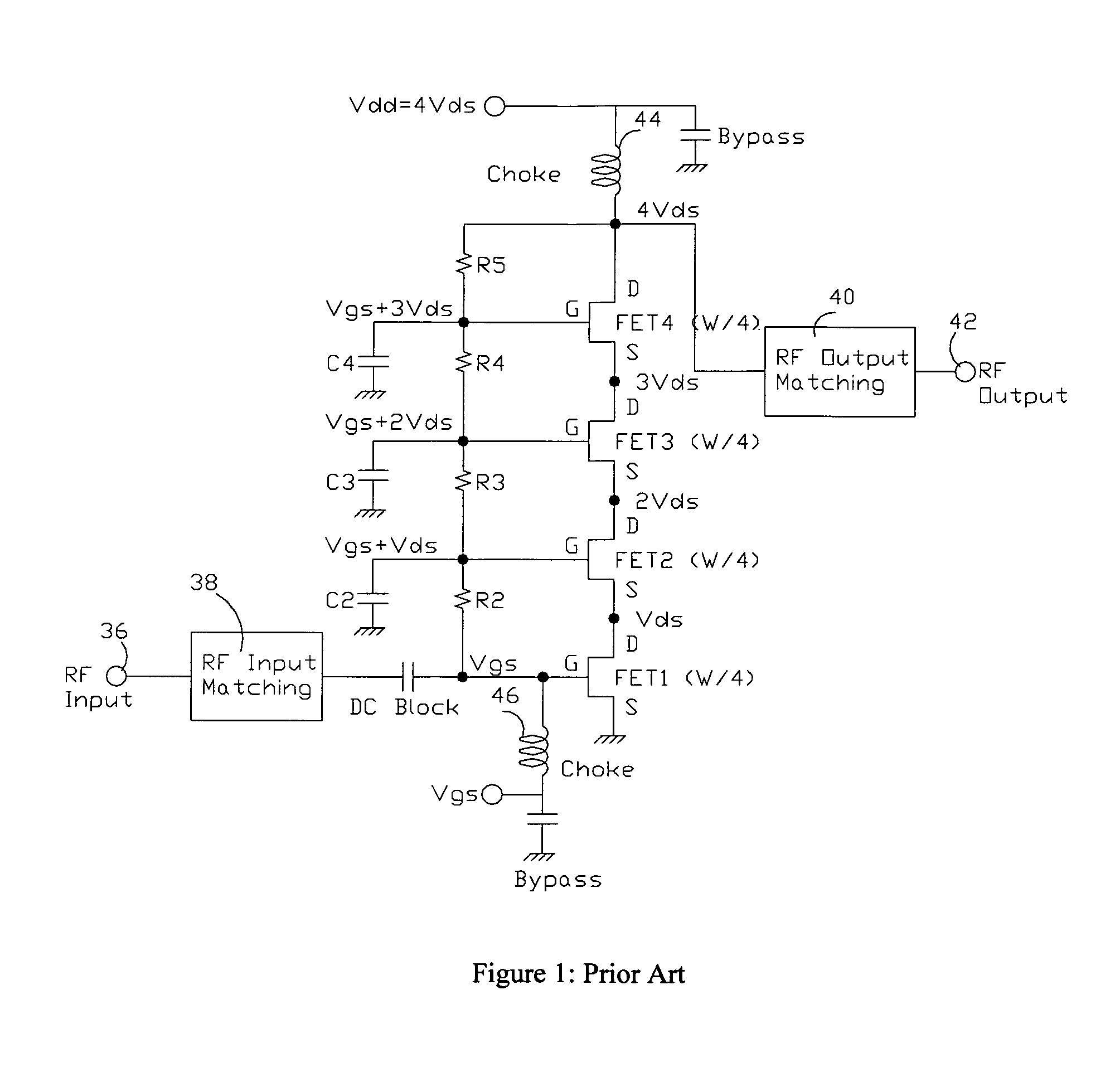
[0020]FIG. 1 shows the circuit shown in FIG. 2 of the '367 patent, which is incorporated herein by this reference. This prior art circuit is referred to herein as a high-voltage high-power (HiVP) amplifier. In the implementation shown, four essentially identical FETs, FET1-FET4, are connected in series, with the drain terminal D of FET1 connected directly to the source terminal S of FET2, and the drain terminal D of FET2 connected directly to the source terminal S of FET3, and so on. The input signal is connected to the amplifier at an input terminal 36, and passes through a single input matching network 38 to the gate terminal G of the first transistor FET1 in the series. The drain terminal D of FET4, the last transistor in the series, is connected through a single output matching network 40 to the output terminal 42 of the amplifier. The output signal from FET4 is also fed back via series-connected resistors R2-R5 to the gate terminals G of each of FETs 1-4. Capacitors C2-C4 adjus...


PUM


Abstract

The invention is an improvement in microwave and millimeter wave amplifiers. Capacitors are connected in parallel with the source and drain terminals of all of the amplifying elements in a series of such elements except the first, compensating for current leakage due to gate capacitance. This results in improved synchronism of the amplifying elements, and improved overall efficiency and circuit performance.

Description

FIELD OF THE INVENTION[0001]This application is directed to improvements in amplifiers intended for use at high frequencies, e.g., up to 90 GHz and beyond, which exhibit higher efficiency than the prior art.BACKGROUND OF THE INVENTION[0002]In U.S. Pat. No. 6,137,367 (the “'367 patent”), the present inventors disclose certain improvements in high-power amplifiers which result in improved impedance matching to the typical load and thus improved efficiency. The present application discloses further improvements which result in still better efficiency, particularly at higher frequencies, e.g., 3 GHz up to millimeter wave frequencies.SUMMARY OF THE INVENTION[0003]According to the present invention, capacitors of specific values are connected in parallel with the drain and source terminals of each of the field-effect transistors (“FETs”) connected in series according to the '367 patent, except the first thereof. This results in improved synchronization of the FETs, which results in improv...

Claims


Application Information

Patent Timeline
Patent Type & Authority Patents(United States)
IPC IPC(8): H03F3/04
CPCH03F1/0205H03F3/423H03F3/193H03F2200/18
Inventor EZZEDDINE, AMINHUANG, HO C.
Owner AMCOM COMM
Why Eureka
Try Eureka