Digital broadcast reception apparatus

a digital broadcast and reception technology, applied in the field of digital broadcast reception apparatus, can solve the problems of abnormal reception, inability to carry out demodulation or decoding, and inability to find normal reception, so as to achieve the effect of reliably finding a digital broadcas

Inactive Publication Date: 2013-05-07
FUNAI ELECTRIC CO LTD
View PDF11 Cites 0 Cited by
  • Summary
  • Abstract
  • Description
  • Claims
  • Application Information

AI Technical Summary

Benefits of technology

[0012]The invention has an object of providing a digital broadcast reception apparatus which, when a channel setting is carried out, can also reliably find a digital broadcast on a channel which has been impossible to find due to a size of received power.

Problems solved by technology

Meanwhile, the received power of the broadcast signal varies depending on the channel frequency or reception environment of the broadcast signal and, in the analog broadcasting, even in the event that the received power thereof is large, it is possible to carry out a demodulation and decoding of the broadcast signal but, in the digital broadcasting, in the event that the received power is large beyond the tolerance level, it is not possible to carry out the demodulation or the decoding.
That is, as a modulation method used in the digital broadcasting, a digital modulation method is used, such as a PSK (Phase Shift Keying), an 8-VSB (Vestigial Side Band) or a QAM (Quadrature Amplitude Modulation), but, an error occurs when the demodulation is carried out by means of the demodulation method, causing a reception abnormality.
For this reason, regarding a digital broadcast on a channel on which the received power of the received broadcast signal is large, a normal reception cannot be found due to an error occurring at a time of the demodulation, and the channel setting becomes impossible.
However, in the event that a digital broadcast on a channel, on which the received power of the broadcast signal is large beyond the tolerance level, has been received, it is impossible to demodulate and decode the received broadcast signal.

Method used


Image

  • Digital broadcast reception apparatus
  • Digital broadcast reception apparatus
  • Digital broadcast reception apparatus

Examples


Embodiment Construction

[0024]A description will be given of an embodiment of the invention, referring to the drawings. In the embodiment, a description will be given, as an example, of a digital broadcast reception apparatus which receives a broadcast signal which, as well as being transmitted in each of a UHF band and a VHF band, is digitally modulated, but it is also acceptable that it receives a broadcast signal using a band other than the UHF band and the VHF band, or only one of the UHF band and the VHF band.

Configuration of Digital Broadcast Reception Apparatus

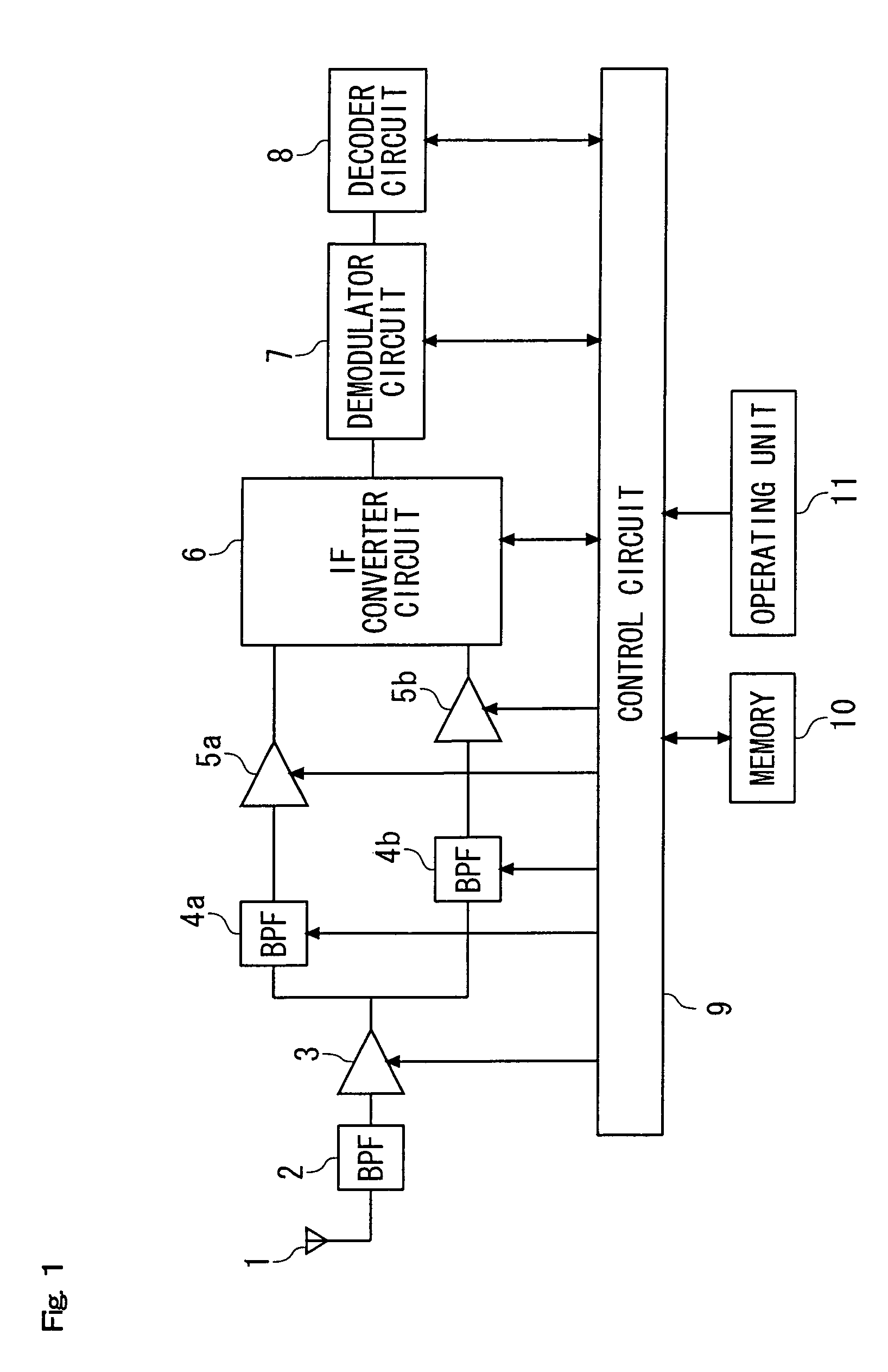
[0025]FIG. 1 is a block diagram showing an internal configuration of the digital broadcast reception apparatus of the embodiment. The digital broadcast reception apparatus shown in FIG. 1 includes an antenna 1 through which are received radio frequency (RF) signals which are digital broadcast signals, a band-pass filter (BPF) 2 which extracts a signal in a service band of a digital broadcast from the RF signals received through the antenna 1, ...


PUM


Abstract

In a digital broadcast reception apparatus, a presetting operation is carried out and, when the presetting operation is carried out, a normal reception of a broadcast signal on a channel, which can be received in an area in which the apparatus is installed, and the normal reception of which cannot be found in the event that a gain in a gain switching amplifier is of an initial value, is made possible by a switching and setting of a gain in each VGA 3, 5a and 5b being carried out by means of a control circuit 9 or an operating unit 11.

Description

[0001]This application is based on Japanese Patent Application No. 2007-011177 filed on Jan. 22, 2007, the contents of which are hereby incorporated by reference.BACKGROUND OF THE INVENTION[0002]1. Field of the Invention[0003]The present invention relates to a digital broadcast reception apparatus which receives a digital broadcast, and particularly to a digital broadcast reception apparatus which can carry out a channel selection and setting for each area.[0004]2. Description of the Related Art[0005]In recent years, along with the development of broadcast communication technology and code compression technology, each kind of broadcast has also become increasingly digitalized, and a broadcasting technology has shifted from analog broadcasting to digital broadcasting. In accordance with digitalization in a broadcast sector, in a broadcast reception apparatus which receives a broadcast too, a specification thereof has been changed to a specification for receiving the digital broadcast...

Claims


Application Information

Patent Timeline
Patent Type & Authority Patents(United States)
IPC IPC(8): H04N5/50H04B1/16H04N5/44
CPCH03G3/3052
Inventor FUKUI, MASANAO
Owner FUNAI ELECTRIC CO LTD
Why Eureka
Try Eureka