Electropneumatic Control System and Position Controller for Such a System

a technology of electropneumatic control and pneumatic actuator, which is applied in the direction of fluid-pressure actuator components, servomotor components, servomotor components, etc., can solve the problems of undesirable behavior, significant additional cost/complexity of feeding the signal back to the electropneumatic position controller, and the flow rate of the valves incorporated, so as to achieve simple and reliable manner, reliably find the setting, and reduce the effect of pressure variations

Active Publication Date: 2019-09-19
SIEMENS AG
View PDF6 Cites 0 Cited by
  • Summary
  • Abstract
  • Description
  • Claims
  • Application Information

AI Technical Summary

Benefits of technology

[0008]The advantage of the invention is that an operating mode for the electropneumatic control system has been created in which an operator is guided to a suitable adjustment of a bypass valve in a particularly simple and reliable manner.
[0009]Finding a suitable setting of the bypass valve is particularly important because of the following problems: if the bypass valve on the booster is completely closed, usually even minimal pressure variations of the first pneumatic control signal affect the output of the booster, as the latter delivers pressure variations in an amplified manner to its output, i.e., onto the second pneumatic control signal. This disadvantageously means that a valve provided with a pneumatic actuator is likely to vibrate, because fine control of the actuator position is not possible using small amounts of air in such a setting. Wide opening of the bypass valve results in a slow response of the booster and may likewise cause vibrations because of the associated delay in the position control loop.
[0010]Opening of the bypass valve by a certain amount allows the pressure variations on the pneumatic control signals to be attenuated, because minimal variations can now be compensated via the bypass valve. However, finding a bypass valve setting well suited for this purpose has hitherto proved to be comparatively difficult. The position controller had to be caused to move the pneumatic actuator via manual input. With the actuator stopped, an operator had to visually assess the behavior of the pneumatic actuator or rather of the valve operated thereby. If actuator overshoot could be detected, then the bypass valve on the volume booster was opened further. As this procedure only permitted a qualitative assessment of the transient response, the finding of a throttle valve setting with minimal overshoot was rather left to chance.
[0011]In contrast, the advantage of the inventive electropneumatic control system is that the respective overshoot when moving to a new position is quantitatively determined and displayed to the operator. This enables the operator, by varying the adjustment of the throttle valve, to reliably find the setting resulting in a low or even the lowest overshoot value and thus maintaining a good transient response of the electropneumatic control system.
[0012]The varying of the setting of the bypass valve can be performed manually by an operator between the individual positionings or using automatic adjustment mechanisms, e.g., via a suitably controlled stepping motor. For automatic adjustment, it may be advisable to likewise provide the operator with a display of characteristic values for the respective settings of the bypass valve that were used to determine the different overshoot values when moving to new positions.
[0013]As the pneumatic characteristics of the control system for supplying air to and exhausting air from an actuator chamber may differ from one another, or as a plurality of boosters are used in the case of double-acting actuators, it may also be advantageous to determine a first group of overshoot values for movement in a first direction and a second group of overshoot values for movement of the actuator in a second direction counter to the first direction and to find for each group a setting of the bypass valve(s) with low overshoot based on the overshoot values respectively assigned.

Problems solved by technology

As the air flow rate of the valves incorporated in the electropneumatic position controller is limited, large pneumatic actuators often require the installation of a volume booster to achieve a desired positioning speed.
However, the use of boosters in electropneumatic control system can disadvantageously result in an undesirable behavior, particularly when the position of the actuator changes.
However, the generation of the feedback signal in the booster and the paths for feeding the signal back to the electropneumatic position controller involve significant additional cost / complexity.
This cost / complexity is considered to be necessary even if a so-called bypass valve is used.
This disadvantageously means that a valve provided with a pneumatic actuator is likely to vibrate, because fine control of the actuator position is not possible using small amounts of air in such a setting.
Wide opening of the bypass valve results in a slow response of the booster and may likewise cause vibrations because of the associated delay in the position control loop.
However, finding a bypass valve setting well suited for this purpose has hitherto proved to be comparatively difficult.

Method used


Image

  • Electropneumatic Control System and Position Controller for Such a System
  • Electropneumatic Control System and Position Controller for Such a System
  • Electropneumatic Control System and Position Controller for Such a System

Examples


Embodiment Construction

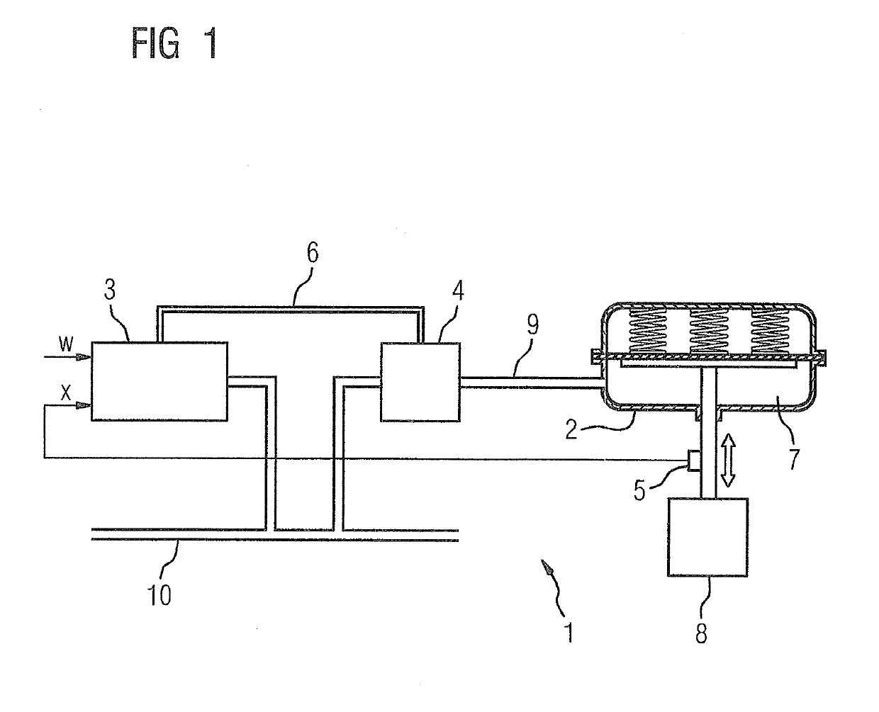
[0025]An electropneumatic control system 1 for a pneumatic actuator 2 comprises, as shown in FIG. 1, an electropneumatic position controller 3, a volume booster 4 and a position sensor 5 for acquiring an actual value x of the position of the pneumatic actuator 2. The position controller 3 is prescribed a setpoint value w for the actuator position e.g. by an automation device or control system (not shown in FIG. 1 for the sake of clarity). During controlled operation of the position controller 3, the setpoint value w is compared with the currently measured actual value x of the position and, depending on the deviation thus formed, a first pneumatic control signal 6 is generated to reduce the deviation. The exemplary embodiment shows a single-acting pneumatic actuator 2 having a comparatively large pressure chamber 7, and which is used to actuate a valve 8. However, in order to achieve short closing and opening times of the valve 8, the air flow rate that the position controller 3 pro...


PUM


Abstract

An electropneumatic control system for a pneumatic drive and electropneumatic position controller for the system, wherein a volume flow booster having a bypass valve is downstream of the position controller to increase the air capacity, where the pneumatic drive is run in a new operating mode multiple times at maximum air capacity in a first direction to support an operator in adjusting the bypass valve, and where upon exceeding a specified position, the air capacity is set to zero, an overshoot value of the pneumatic drive is determined and output for the operator on a display such that by varying adjustment of the bypass valve, the operator can find and set an adjustment of the valve having low overshoot such that with an adjustment found in such a manner, the transition behavior of the control system can be significantly improved without additional effort.

Description

CROSS-REFERENCE TO RELATED APPLICATIONS[0001]This is a U.S. national stage of application No. PCT / EP2017 / 078923 filed Nov. 10, 2017. Priority is claimed on German Application No. 102016222153.1 filed Nov. 11, 2016, the content of which is incorporated herein by reference in its entirety.BACKGROUND OF THE INVENTION1. Field of the Invention[0002]The invention relates to an electropneumatic control system for a pneumatic actuator, an electropneumatic position controller for such a control system, a method for operating the electropneumatic control system, a computer program having program code instructions executable by a microcontroller of a position controller for implementing the method, and a computer program product comprising such a computer program.2. Description of the Related Art[0003]EP 1 769 159 B1 discloses an electropneumatic control system having a position controller that is suitable for controlling the position of an associated final control element, e.g., a valve or da...

Claims


Application Information

Patent Timeline
Patent Type & Authority Applications(United States)
IPC IPC(8): F15B19/00F15B13/042
CPCF15B2211/6656F15B5/006F15B2211/6336F15B2211/8613F15B19/005F15B13/042F15B21/082F15B2211/30565F15B2211/40515F15B19/002
Inventor STEGMANNS, ROBERT MARKUS
Owner SIEMENS AG
Why Eureka
Try Eureka