
Electronic article surveillance system

a technology of electronic articles and surveillance systems, applied in the field of electronic article surveillance systems, can solve the problems of system not allowing to associate a particular data carrier with the first or the second zone, and achieve the effect of appropriate handling

Active Publication Date: 2013-05-14
NXP BV
View PDF24 Cites 15 Cited by
  • Summary
  • Abstract
  • Description
  • Claims
  • Application Information

AI Technical Summary

Benefits of technology

The invention provides a system for electronic article surveillance that allows data carriers to be associated with specific zones and allows the electronic article surveillance status of those zones to be tested. This enables the exclusion of data carriers that do not have a specific electronic article surveillance status from handling the testing of other zones. The system also allows for the communication of test results in real-time or at a later time, and ensures the protection of zone information from fraudulent use or manipulation. Additionally, the system allows for the creation and handling of a hierarchical structure of electronic article surveillance zones.

Problems solved by technology

The prior art system shows the problem that such overlapping or superposition of signals does allow to define relatively large electronic article surveillance zones in which data carrier that are located either in the first zone or in the second zone do show a different behavior in the meaning of responding or not responding to a message signal.
On the other hand such a system does not allow to associate a particular data carrier with the first zone or with the second zone, because the different electronic article surveillance zones are solely defined by the signals produced either by the read / write station or by the jamming apparatus and the superposition of these field, which defines one zone being different from another zone that does not show a superposition of said signals.

Method used


Image

  • Electronic article surveillance system
  • Electronic article surveillance system
  • Electronic article surveillance system

Examples


Embodiment Construction

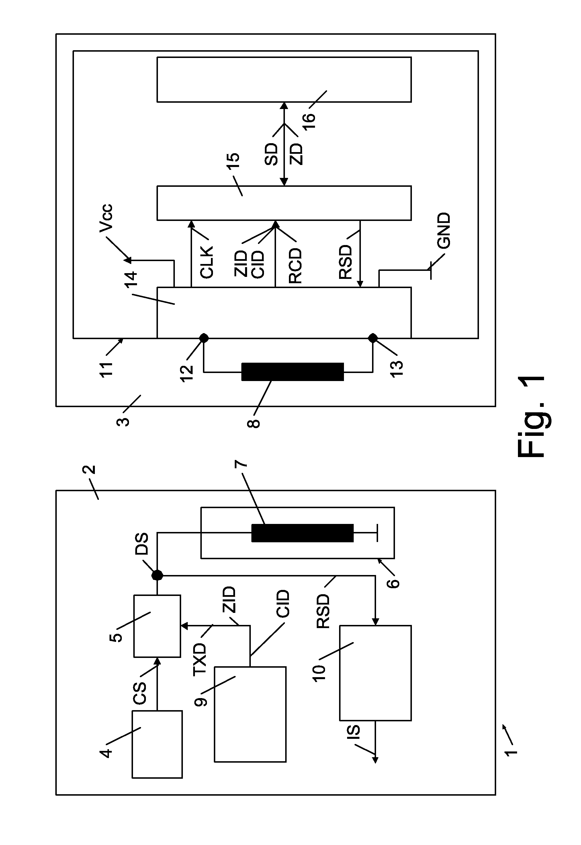
[0041]FIG. 1 shows an electronic article surveillance system that will be called system 1 in the following description, which system 1 comprises a read / write station that will be called station 2 in the following description and which system 1 comprises a data carrier 3. The system 1 is designed for electronic article surveillance, which will be elaborated in details herein below.

[0042]The station 2 comprises an oscillator stage 4 that is designed to generate a carrier signal CS for the purpose of contact-less communication with the data carrier 3. The station 2 further comprises modulation means 5 that are designed to receive the carrier signal CS and transmission data TXD and to modulate the carrier signal CS dependent on the transmission data TXD. The station 2 further comprises station transmission means 6 of which only a communication coil arrangement 7 is schematically shown in FIG. 1. The man skilled in the art will immediately understand that a tuned resonance circuit and a ...


PUM


Abstract

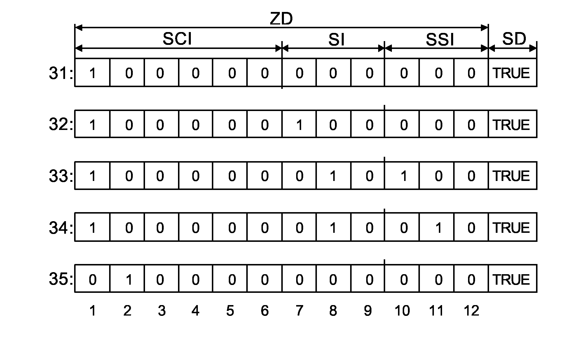
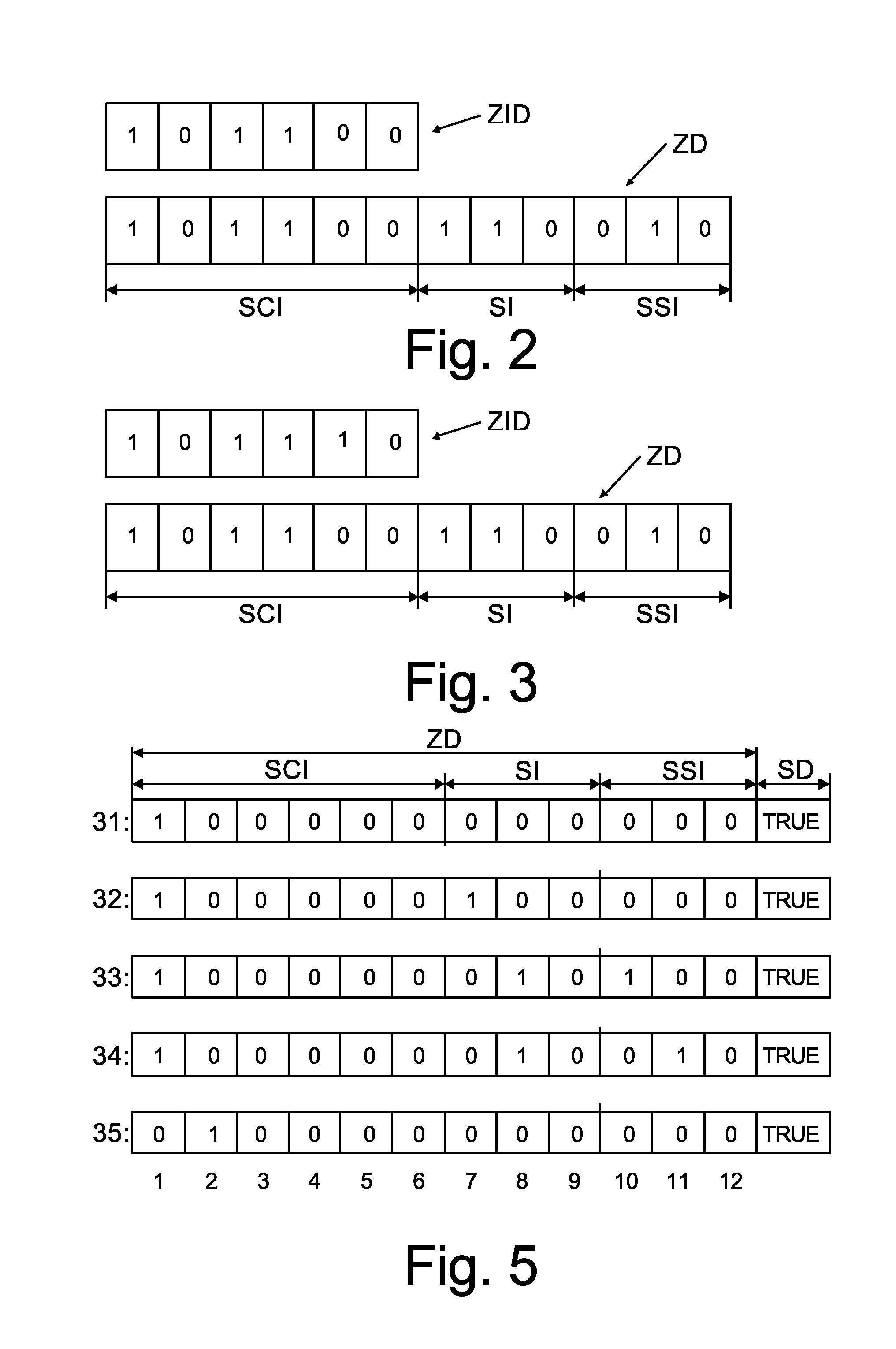
An electronic article surveillance system (1) comprises a read / write station (2; 217, 218, 220-224) that is designed to communicate an electronic article surveillance status test-request command comprising zone information that indicates an electronic article surveillance zone for which an electronic article surveillance status that is assigned to said zone is to be tested, and further comprises a data carrier (3; 31-35) having a circuit (11) that is designed to store status data (SD) for indicating whether an electronic article surveillance status is active and to store zone data (ZD) for specifying at least one electronic article surveillance zone to which the electronic article status is assigned, the data carrier (3; 31-35) being further designed to test whether said stored status is active for the electronic article surveillance zone to which it is assigned in the case that this zone is indicated by the zone information provided by the read / write station (2; 217, 218, 220-224).

Description

FIELD OF THE INVENTION[0001]The invention relates to a circuit for a data carrier, which data carrier comprises data carrier transmission means that are designed for a contact-less communication with a read / write station.[0002]The invention further relates to a data carrier comprising data carrier transmission means, which data carrier transmission means are designed for a contact-less communication with a read / write station, and a circuit according to the preceding paragraph.[0003]The invention further relates to a read / write station that is designed for a contact-less communication with a data carrier.[0004]The invention further relates to an electronic article surveillance system comprising at least one read / write station according to the preceding paragraph and at least one data carrier according to the second paragraph.[0005]The invention further relates to a method of testing whether an electronic article surveillance status that is represented by means of data stored in a dat...

Claims


Application Information

Patent Timeline
Patent Type & Authority Patents(United States)
IPC IPC(8): H04N7/18G06F17/30H04N9/47G06F7/00
CPCG08B13/2402G08B21/0275G08B13/24G08B13/00G08B21/24
Inventor HUBMER, PAULSCHWAR, CHRISTIAN
Owner NXP BV
Learn More