
Pupil-expanded volumetric display

Inactive Publication Date: 2013-05-14
KESSLER DAVID
View PDF3 Cites 8 Cited by
  • Summary
  • Abstract
  • Description
  • Claims
  • Application Information

AI Technical Summary

Benefits of technology

The present invention offers a precise and realistic image that can be used for guiding navigation and other applications. This image has the proper depth of field and perspective, allowing for accurate and trustworthy guidance.

Problems solved by technology

While stereoscopic and auto-stereoscopic imaging apparatus provide the appearance of 3-D, however, the imaging methods that are used provide only a limited number of psychological depth cues.
Stereoscopic and auto-stereoscopic systems simulate convergence which is an aspect of depth position, but fail to provide the visual cue for focal accommodation.
Overall, stereoscopic depth cues can tend to conflict with physical cues, leading to visual confusion and fatigue, as well as to misjudgment of distance, velocity, and shape.
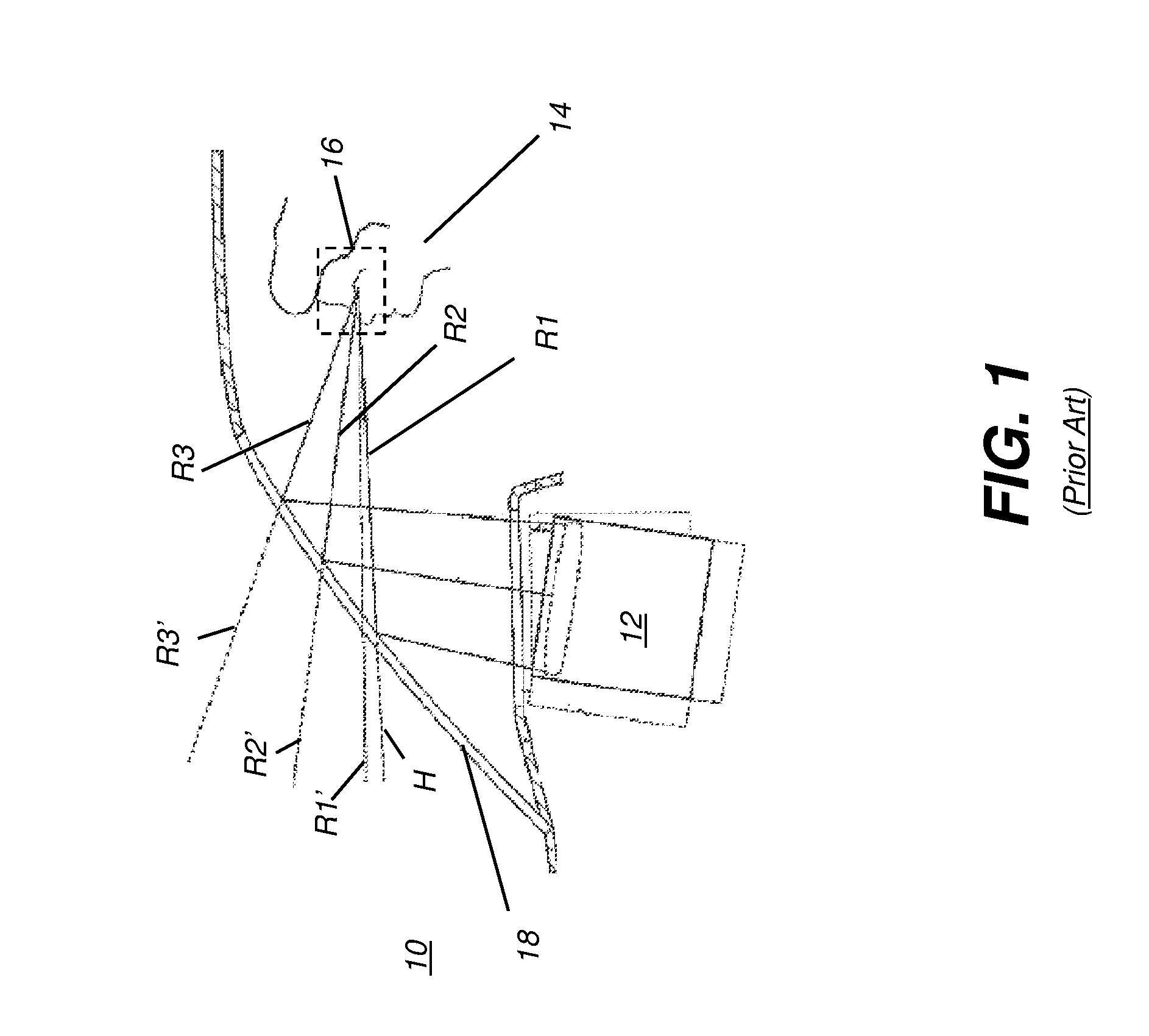
For reasons such as these, stereoscopic techniques can be inappropriate for navigational guidance applications, such as for use in heads-up displays.
While the methods and apparatus taught in the ‘1707 Grabowski et al. application provide the benefits of volumetric imaging for improved navigational guidance, however, implementation of such a system comes at a cost.
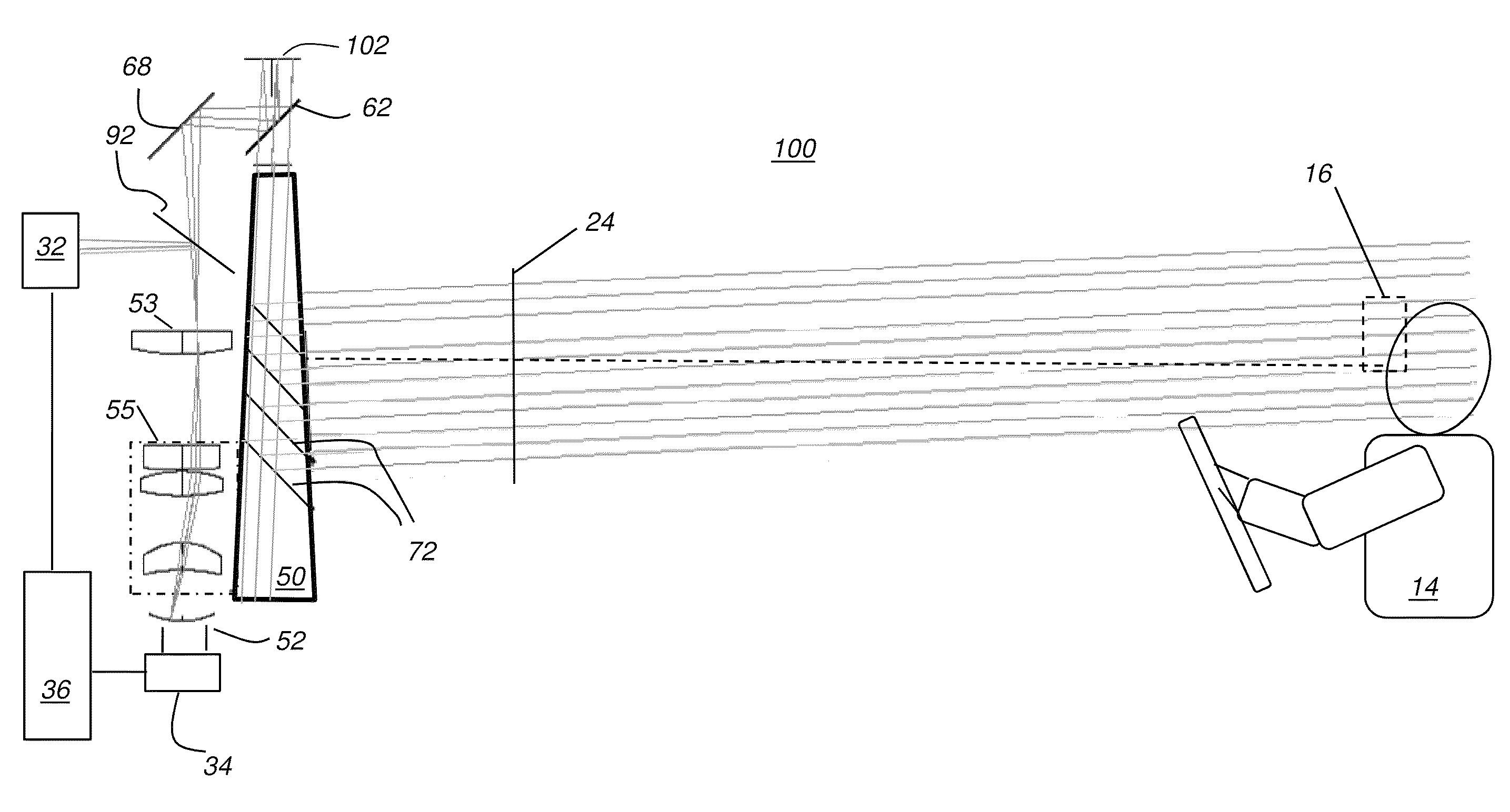
The optical system needed to support volumetric imaging is hampered by its size requirements and by the complexity of its aspherical optical components.
Lenses used are characterized by large diameters, resulting in high cost, placement constraints, and difficulty of mounting.

Method used


Image

  • Pupil-expanded volumetric display
  • Pupil-expanded volumetric display
  • Pupil-expanded volumetric display

Examples


Embodiment Construction

[0033]The present description is directed in particular to elements forming part of, or cooperating more directly with, apparatus in accordance with the invention. It is to be understood that elements not specifically shown or described may take various forms well known to those skilled in the art.

[0034]Figures shown and described herein are provided in order to illustrate key principles of operation and component relationships along their respective optical paths according to the present invention and are not drawn with intent to show actual size or scale. Some exaggeration may be necessary in order to emphasize basic structural relationships or principles of operation. Some conventional components that would be needed for implementation of the described embodiments, such as various types of optical mounts, for example, are not shown in the drawings in order to simplify description of the invention itself. In the drawings and text that follow, like components are designated with li...


PUM


Abstract

A volumetric imaging apparatus has a volumetric image generator with a light source, a light modulator, and a display surface. The volumetric image generator is energizable to form, on the display surface, an image over a range of focal positions at the entrance pupil of an optical system. The optical system is disposed to direct light from the image to a one-dimensional pupil expander. A combiner surface is disposed in the path of output light from the pupil expander for displaying the volumetric image.

Description

CROSS REFERENCE TO RELATED APPLICATIONS[0001]Priority is claimed from U.S. Ser. No. 61 / 172,701, provisionally filed on Apr. 24, 2009, entitled “A Pupil-Expanded Volumetric Display” in the name of David Kessler and incorporated herein by reference.FIELD OF THE INVENTION[0002]This invention generally relates to volumetric imaging and more particularly relates to a volumetric imaging apparatus using a pupil expander in a single dimension.BACKGROUND OF THE INVENTION[0003]Three-dimensional (3-D) imaging has recognized value in a number of applications as diverse as medical imaging, visualization technologies, and navigational guidance systems. Advantaged over 2-D display methods and devices, 3-D imaging techniques help to improve how well image data can be represented to a viewer and provide useful characteristics that allow a measure of depth perception that can be particularly valuable in such applications.[0004]A number of 3-D imaging methods are available for more closely representin...

Claims


Application Information

Patent Timeline
IPC IPC(8): G02B27/14G02B30/25
CPCG02B27/0081G02B27/0103G02B27/2285G02B3/08G02B5/02G02B27/283G02B2027/0123G02B2027/0127G02B2027/0134G02B30/54
Inventor KESSLER, DAVID
Owner KESSLER DAVID
Learn More