Variable focus lens and spectacles

a focus lens and lens technology, applied in the field of variable focus lenses and spectacles, can solve the problems of prone to damage to separate ducts, inconvenient use of this lens, etc., and achieve the effect of simple adjustmen

Inactive Publication Date: 2013-05-14
ADLENS
View PDF57 Cites 17 Cited by
  • Summary
  • Abstract
  • Description
  • Claims
  • Application Information

AI Technical Summary

Benefits of technology

[0010]It is further preferred for the front cover (and, if appropriate, the rear cover) to be formed with an annular projection that fits into the step of the profile of the ring. This construction allows a stronger joint between the cover and the ring.
[0021]A cosmetic knob may be provided on said adjuster to improve its appearance. If such a knob is provided, then it is preferred for a clutch mechanism to be disposed between the adjuster and the knob, to prevent damage to the mechanism from overtightening.

Problems solved by technology

If this lens is to be used in spectacles, the spectacle frames for the lenses must allow the lens to be accessed by the syringe, and it will be appreciated that use of this lens can be rather inconvenient in some circumstances.
Further, there is no need to provide a separate duct connecting the reservoir with the lens cavity; in the past, such separate ducts have been prone to damage, and have been capable of interfering with the folding of the spectacles.

Method used


Image

  • Variable focus lens and spectacles
  • Variable focus lens and spectacles
  • Variable focus lens and spectacles

Examples


Embodiment Construction

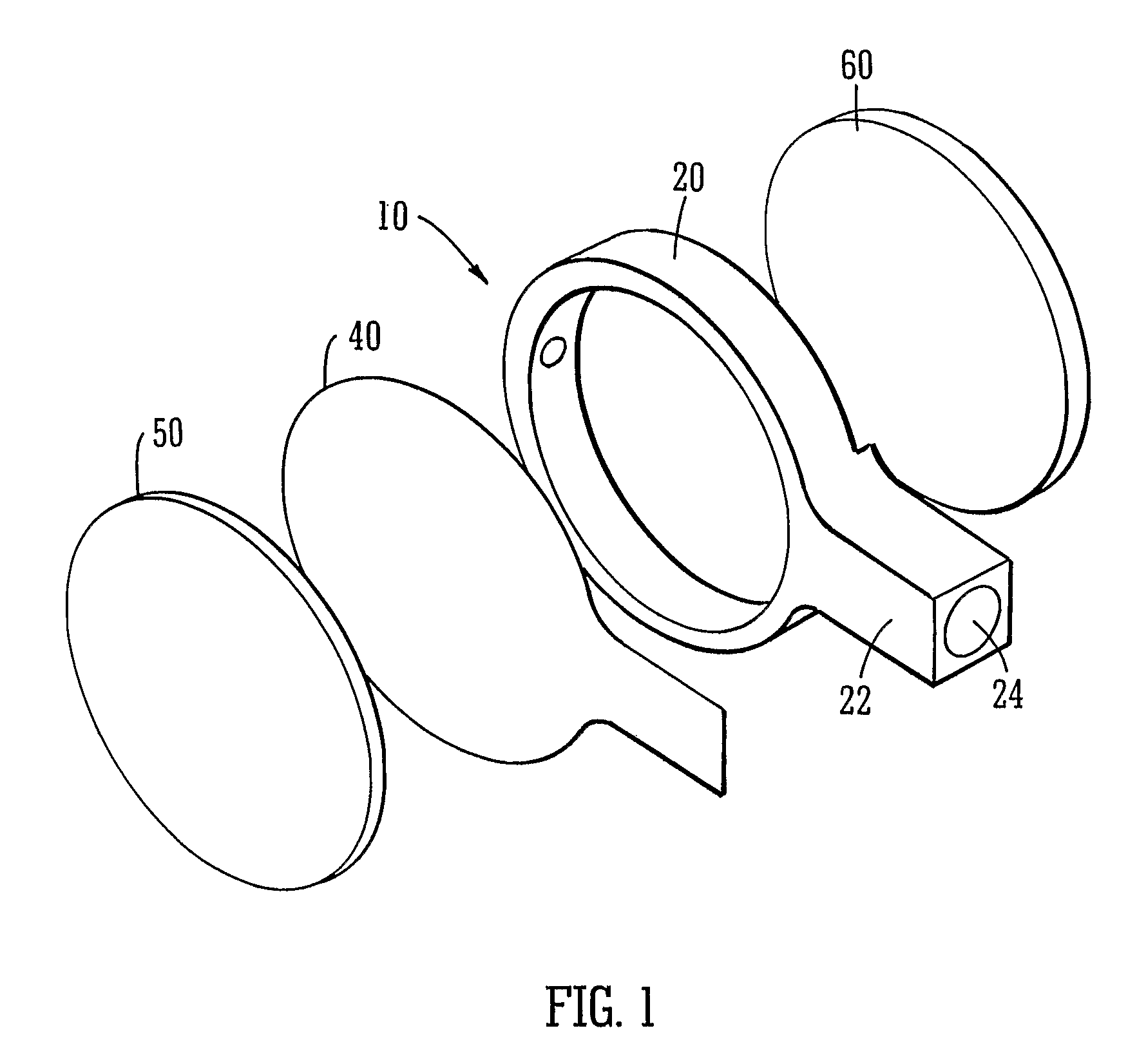
[0035]FIG. 1 shows an earlier proposed lens 10 with an integral reservoir. The lens is formed from a plastic ring 20, which has an integral extension 22 with a hollow bore 24 therein. A rear cover 60 is attached to the rear of the ring 20, and a flexible membrane 40 is attached to the front of the ring. The ring 20, the rear cover 60 and the flexible membrane 40 between them form a cavity which is filled with liquid; further liquid can be introduced into and removed from the cavity to deform the flexible membrane and thus adjust the power of the lens. A front cover 50 is attached to the flexible membrane for protection.

[0036]The hollow bore 24 of the extension 22 serves as a reservoir, and contains a small amount of liquid which can be used to vary the power of the lens. A piston in the bore can be moved toward and away from the ring, to move liquid into and out of the cavity and thus deform the flexible membrane.

[0037]In order to reduce the amount of fluid required for correction, ...


PUM


Abstract

The invention provides a variable focus lens formed from a ring with a front surface and a rear surface, a flexible membrane is attached to a radially inner part of the front surface, and a front cover is attached to a radially outer part of the front surface, a rear cover is provided on the rear surface of the ring, preferably integral with the ring, so that a variable volume cavity is defined between the flexible membrane, the ring and the rear cover, second flexible membrane can be provided between the ring and the rear cover, where the invention also provides a method of filling a variable focus lens, and an adjustment mechanism for varying the focus of the lens.

Description

TECHNICAL FIELD[0001]The invention relates to a variable focus lens, and to spectacles using the variable focus lens.BACKGROUND[0002]Fluid-filled variable focus lenses are well known. They normally consist of a liquid-filled chamber, at least one face of which is formed by a transparent flexible membrane. As liquid is introduced into or removed from the chamber, the flexible membrane is deformed, and its curvature accordingly changes. This change in curvature leads to a change in the optical characteristics and power of the lens. The power of the lens can thus be varied simply by varying the amount of liquid in the chamber.[0003]One type of prior art variable focus lens is disclosed, for example, in WO 96 / 38744. In this document, the amount of fluid in the lens is adjusted by inserting a syringe through a bung, and using the syringe to add or withdraw fluid. If this lens is to be used in spectacles, the spectacle frames for the lenses must allow the lens to be accessed by the syring...

Claims


Application Information

Patent Timeline
Patent Type & Authority Patents(United States)
IPC IPC(8): G02B3/12
CPCG02C7/085G02B3/14
Inventor BUCH, JUSTINJOHNSON, WILLIAMNEWBERY, MIRANDAROBERSTON, ANDREWTAYLOR, RICHARDWHITE, JONATHAN
Owner ADLENS
Why Eureka
Try Eureka