
Robotic heliostat calibration system and method

a heliostat and calibration system technology, applied in the field of solar tracking and calibration devices, can solve the problems of heliostat installation flexibility, cost-effective approach, and the factor in the cost of fully loaded systems

Active Publication Date: 2013-05-14
TESLA INC
View PDF29 Cites 12 Cited by
  • Summary
  • Abstract
  • Description
  • Claims
  • Application Information

AI Technical Summary

Benefits of technology

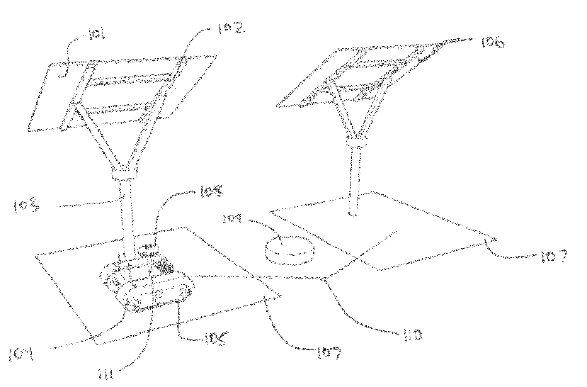
The invention is a robotic controller that can autonomously calibrate and inspect solar surfaces. It uses sensors and a drive system to position itself near a solar surface and gather information about it. The gathered data is then combined with historical data to calibrate the solar surface and determine its health. The robotic controller can discover its position in a global reference frame using various methods such as GPS, triangulation, or natural light camera systems. It can also use its known position to determine the orientation of a solar surface, the non-perpendicularity of its pedestal axis, and if it is aligned to the sun. The robotic controller can communicate the gathered data to a central processing network or other robotic controllers. The invention allows for efficient and accurate calibration and inspection of solar surfaces.

Problems solved by technology

The main problem with the current calibration approach is that in order to obtain an accurate and diverse set of samples, each heliostat must be calibrated relative to an accurately positioned sun or light-sensing device.
For smaller heliostats this approach is not cost-effective as the reflecting area decreases while the amount of labor required per heliostat remains fixed.
This approach is problematic, as it requires precise installation of calibration towers / sensors and places constraints on heliostat installation flexibility that factor into the fully loaded system cost.

Method used


Image

  • Robotic heliostat calibration system and method
  • Robotic heliostat calibration system and method
  • Robotic heliostat calibration system and method

Examples


Embodiment Construction

[0035]A preferred embodiment of the present invention is now described with reference to the figures where like reference numbers indicate identical or functionally similar elements. Also in the figures, the left most digits of each reference number corresponds to the figure in which the reference number is first used.

[0036]Reference in the specification to “one embodiment” or to “an embodiment” means that a particular feature, structure, or characteristic described in connection with the embodiments is included in at least one embodiment of the invention. The appearances of the phrase “in one embodiment” or “an embodiment” in various places in the specification are not necessarily all referring to the same embodiment.

[0037]Some portions of the detailed description that follows are presented in terms of algorithms and symbolic representations of operations on data bits within a computer memory. These algorithmic descriptions and representations are the means used by those skilled in...


PUM


Abstract

A robotic controller for autonomous calibration and inspection of two or more solar surfaces wherein the robotic controller includes a drive system to position itself near a solar surface such that onboard sensors may be utilized to gather information about the solar surface. An onboard communication unit relays information to a central processing network, this processor combines new information with stored historical data to calibrate a solar surface and / or to determine its instantaneous health.

Description

RELATED APPLICATIONS[0001]This application claims priority from U.S. provisional application No. 61 / 419,685 filed on Dec. 3, 2010, U.S. utility application Ser. No. 13 / 118,274 filed May 27, 2011, and US utility application Ser. No. 13 / 182,297 filed Jul. 13, 2011, which are all incorporated by reference herein in their entirety.FIELD OF THE INVENTION[0002]The present invention relates to solar tracking and calibration devices, and in particular tracking systems for photovoltaic, concentrated photovoltaic, and concentrated solar thermal systems that require constant repositioning to maintain alignment with the sun.BACKGROUND OF THE INVENTION[0003]In an attempt to reduce the price of solar energy, many developments have been made with respect to lowering the cost of precisely repositioning and calibrating a surface with two degrees of freedom. In concentrated solar thermal systems, heliostat arrays utilize dual axis repositioning mechanisms to redirect sunlight to a central tower by ma...

Claims


Application Information

Patent Timeline
Patent Type & Authority Patents(United States)
IPC IPC(8): G01D18/00F24S50/20
CPCF24J2/40F24J2/542G01D18/004F24J2002/0084Y10S901/01F24J2002/5462Y02E10/47F24J2002/385H02S50/15F24S50/00F24S30/452F24S2020/16F24S2050/25F24S2030/134H02S50/00Y10S901/14F24S40/90Y02E10/50G01D18/008G05D1/0278
Inventor FUKUBA, DANIELGOBLE, JOSTRUJILLO, SALOMONCURRIER, THOMAS JOSEPHBOKHARI, WASIQ
Owner TESLA INC
Learn More