Arrangement for the adjustment of equipment for a boiler

a technology for adjusting equipment and boilers, which is applied to steam boiler components, lighting and heating apparatus, combustion process, etc., can solve the problems of affecting the efficiency of spreader protection, so as to achieve efficient protection of the spreader

Active Publication Date: 2013-05-21
METSO POWER AB
View PDF30 Cites 5 Cited by
  • Summary
  • Abstract
  • Description
  • Claims
  • Application Information

AI Technical Summary

Problems solved by technology

The atmosphere within the furnace is heavily corrosive for all equipment in the furnace environment, in particular given that the atmosphere also is rapidly changing.
Arrangements and measures in order to protect these critical components are effective only for very small, well-defined volumes, mainly as a result of the chaotic nature of the flow patterns in the furnace and the severe aggression of the thermochemical attack.
The difficulties of protecting the said critical components of the spreader are not made any less by the fact that the shortest distance between the inner surface of the furnace and the mechanical equipment outside of the boiler cannot be made shorter than approximately 0.5 m due to the wall of a modern soda boiler (reactor) consisting of high-pressure tubes on the inside, protective walls, insulation and external cladding, which all together give the significant thickness of wall.
Due to the thickness of the wall, this means also that the region, or the volume, within which the spreader nozzle moves is large, and this in turn means that deviations from the ideal positioning of the spreader nozzle and the ideal pattern of spread will be significant, while at the same time the possibility of efficiently protecting the spreader is significantly made more difficult, or made impossible.
The introduction of such equipment requires a hole to be made in the boiler wall, where the construction of the boiler wall must be altered around the hole, and in those cases in which tubes are integrated into the wall it is necessary to reroute these, giving high costs.

Method used


Image

  • Arrangement for the adjustment of equipment for a boiler
  • Arrangement for the adjustment of equipment for a boiler
  • Arrangement for the adjustment of equipment for a boiler

Examples


first embodiment

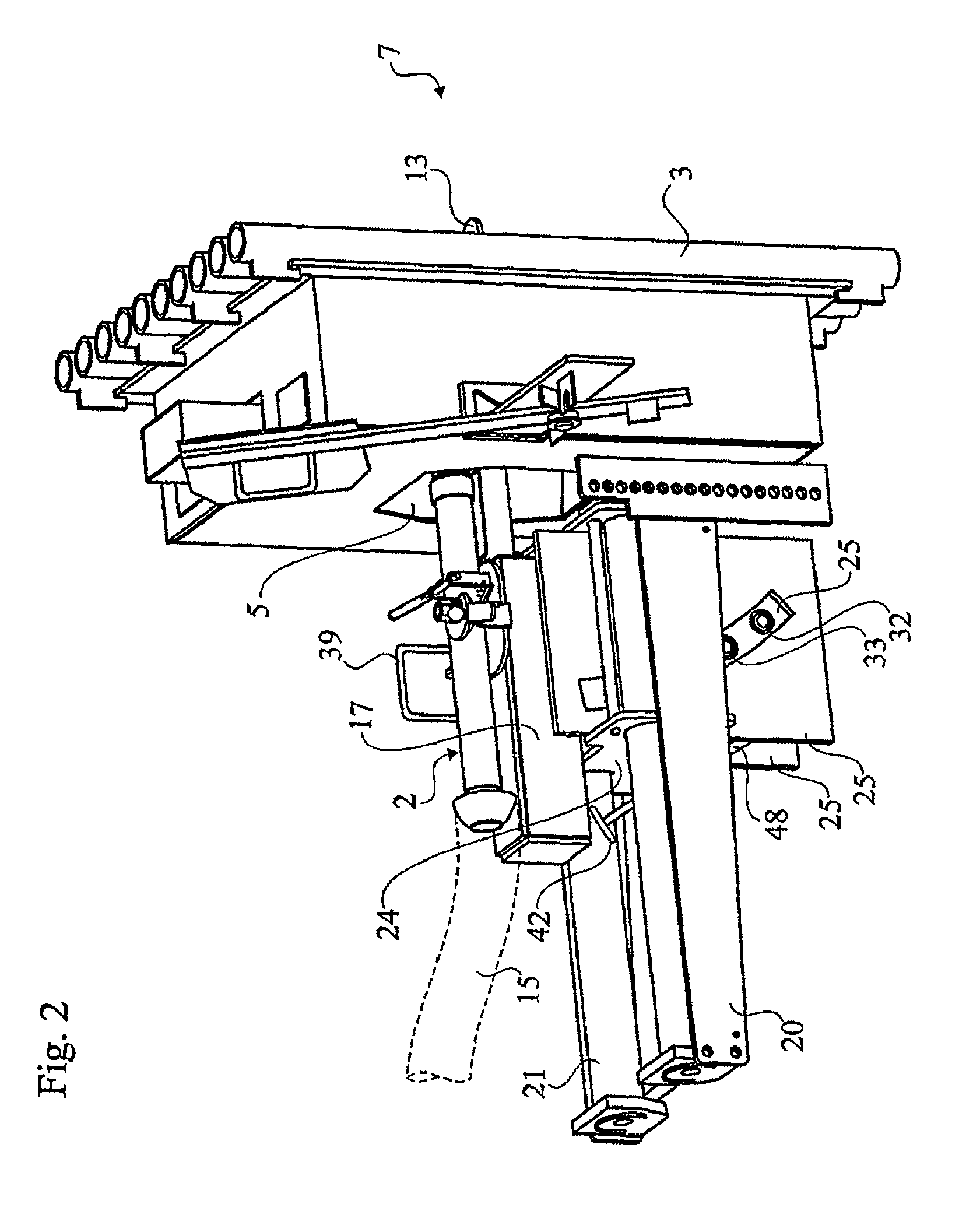
[0033]FIG. 2 illustrates how the principle according to FIG. 1 can be realised, whereby the drawing shows a view in perspective of equipment according to the invention, comprising a spreader unit in its operating position in a soda boiler, of which a part of the boiler wall is shown,

[0034]FIG. 3 shows the equipment according to FIG. 2 in a view seen obliquely from below,

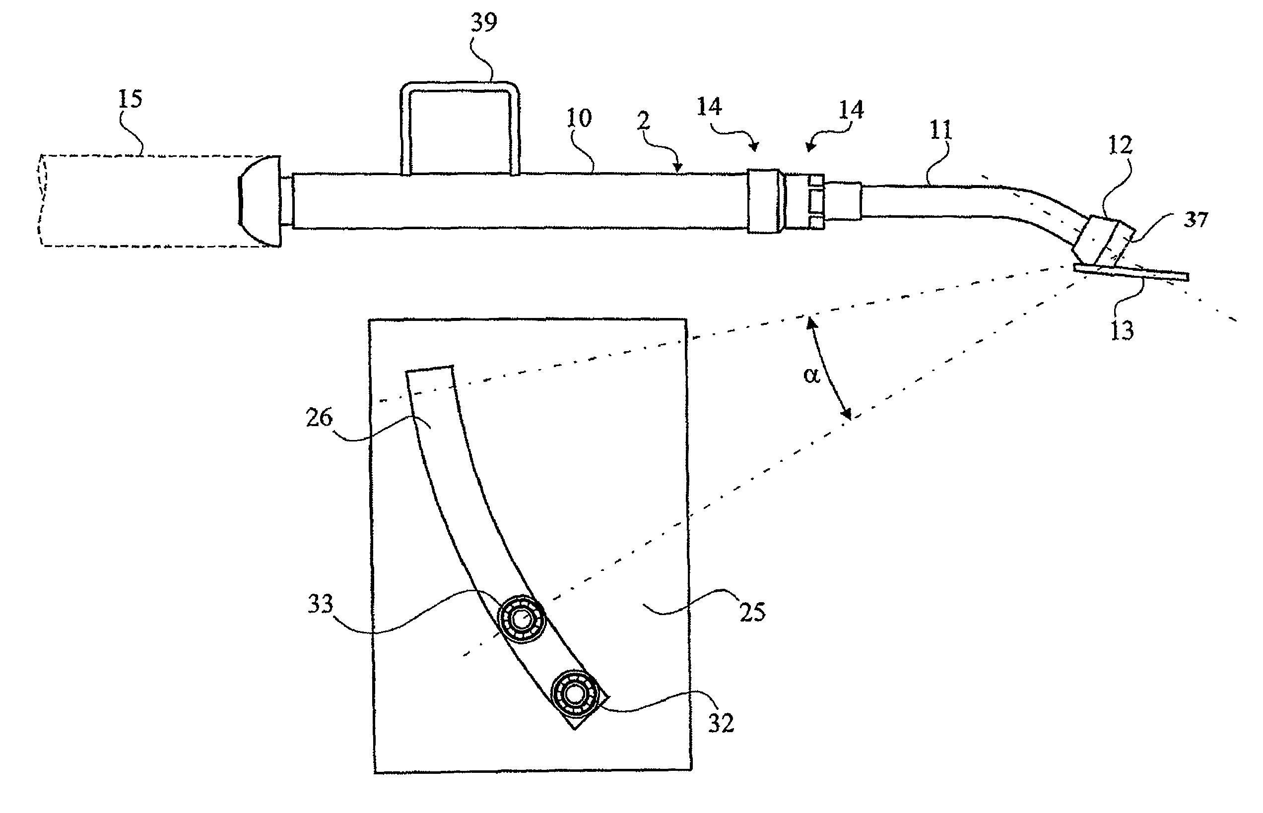
[0035]FIG. 4 illustrates how a spreader unit can be rotated through a certain angle of rotation relative to a fixed member of the equipment according to the embodiment according to FIGS. 2 and 3 around a centre of rotation in the region of the opening of a spreader nozzle in the forward end of the spreader unit,

[0036]FIG. 5 illustrates schematically the equipment and the function of the first embodiment of the invention according to FIGS. 2-4,

[0037]FIG. 6 illustrates how the spreader unit can be rotated according to a second embodiment around the same centre of rotation as that according to the first embodiment, and

third embodiment

[0038]FIG. 7 illustrates how the rotation of the spreader unit can be carried out

fourth embodiment

[0039]FIG. 8 illustrates how the rotation of the spreader unit can be carried out partially freed,

[0040]FIG. 9 illustrates a lower position of the rotation in the fourth embodiment,

[0041]FIG. 10 illustrates an upper position of the rotation in the fourth embodiment.


PUM


Abstract

The arrangement is for positioning equipment in association with an opening in a boiler wall and has a rotation mechanism that rotates the equipment around a virtual rotation axis that lies within the outer wall of the boiler. During the use of a liquor spreader for the introduction of combustible material, the opening of the liquor spreader is arranged in the virtual center of rotation so that the point at which the combustible material is introduced is retained independently of the angle of rotation. The liquor spreader is united either with a glide device or the guide in the rotation mechanism.

Description

PRIOR APPLICATION[0001]This application is a U.S. national phase application based on International Application No. PCT / SE2008 / 050297, filed 17 Mar. 2008.TECHNICAL AREA[0002]The invention relates generally to equipment for boilers with combustion arrangements for liquid fuel, and it has primarily been developed to be used for the combustion of black liquor in soda boilers or in other furnaces for the processing of spent liquor. The invention thus hereby concerns an arrangement for the adjustment of equipment that is associated with the boiler, which equipment can be introduced through a boiler wall.[0003]It is preferable that this arrangement comprises an adjustment of a spreader unit with a nozzle at the forward end of the unit for the distribution of a liquid fuel into a furnace in a boiler. The concept of “boiler” is hereby to include combustion ovens in general. The equipment may also relate to rodding arrangements, soot blowers, cameras or other protective equipment that is to ...

Claims


Application Information

Patent Timeline
Patent Type & Authority Patents(United States)
IPC IPC(8): F22B37/24
CPCD21C11/02F23C5/06F23G7/04F23D11/36F23G2900/54402D21C11/12F23G2209/101
Inventor HERSTAD, OLATILLANDER, ROBERTLINDELL, HENRICKNILSSON, BENGTVULLI, TIMO
Owner METSO POWER AB
Why Eureka
Try Eureka