Industrial frame rack support assembly

a technology for supporting assemblies and racks, which is applied in the direction of display hangers, dismountable cabinets, cabinets, etc., can solve the problems of time-consuming warehouse personnel, prone to being knocked out, skewed or otherwise misaligned, etc., and achieves the effect of convenient removal and reusability

Active Publication Date: 2013-05-21
LIVING STYLE B V I LTD
View PDF27 Cites 54 Cited by
  • Summary
  • Abstract
  • Description
  • Claims
  • Application Information

AI Technical Summary

Benefits of technology

[0009]The cross bars extend between the deck beams such that flanges at the ends thereof overlap the top of the deck beams. The flanges include a tab that extends downwardly to engage with an opening on the top of the deck beams. The lateral support further includes a stabilizer that is fastened to the side wall of the deck beams to prevent rolling or dislodgement of either member.
[0010]It is therefore an object of the present invention to provide an improved system for attaching the structural members of a shelving rack support frame. It is a further object of the present invention to provide an improved cross bar attachment used to create the framing for storage shelves. It is still a further object of the present invention to provide cross bars that are readily removable and reusable yet can be locked or secured against undesired movement and rolling to create a shelf that properly supports loads.

Problems solved by technology

However, in this configuration, the slats are prone to being knocked-out, skewed or otherwise misaligned between the deck beams.
If this shifting or knock-out of one or more slats is unknown to the warehouse personnel, subsequent placement of a load could result in the load falling, leading to injury to the personnel and / or damages to the load, equipment or rack structure.
At best, making sure that the slats are properly positioned between the deck beams is time consuming for the warehouse personnel.
Although an improvement, this method has disadvantages such as increased construction costs and decreased flexibility.
In the past, it has been found that where a decking panel structure has been installed in a shelving rack structure, there is some tendency for the deck beams and cross bars supporting the shelving rack structure to bow in such a way that the structural members tend to roll and / or move apart.
Where the load is heavy enough, the decking panel structure comprising the wood or steel decking, as a result of the movement of the structural members, tends to drop off of the beams.
While welded racks may be strong, they cannot be easily disassembled for moving and the labor involved in welding them together is substantial.
Bolted racks, while easily assembled, exhibit the additional problem that any looseness in the beam to column connection will result in a leaning, wobbling rack.
This in turn induces higher stresses in many of the components which might cause collapse of a heavily loaded rack.
Also, problems may arise because of irregularities in the floor of the warehouse or other place where the rack is positioned.
This, along with small errors in the length and width of the beams and columns as well as the positioning of bolt holes therein, can result in the creation of unpredictable positional variations in the beams and columns as one attempts to affix them together.
This, in turn, may create significant difficulties in getting a tightly bolted connection between the beams and columns, since the parts may not quite fit precisely together because of the unpredictable positional variations.

Method used


Image

  • Industrial frame rack support assembly
  • Industrial frame rack support assembly
  • Industrial frame rack support assembly

Examples


Embodiment Construction

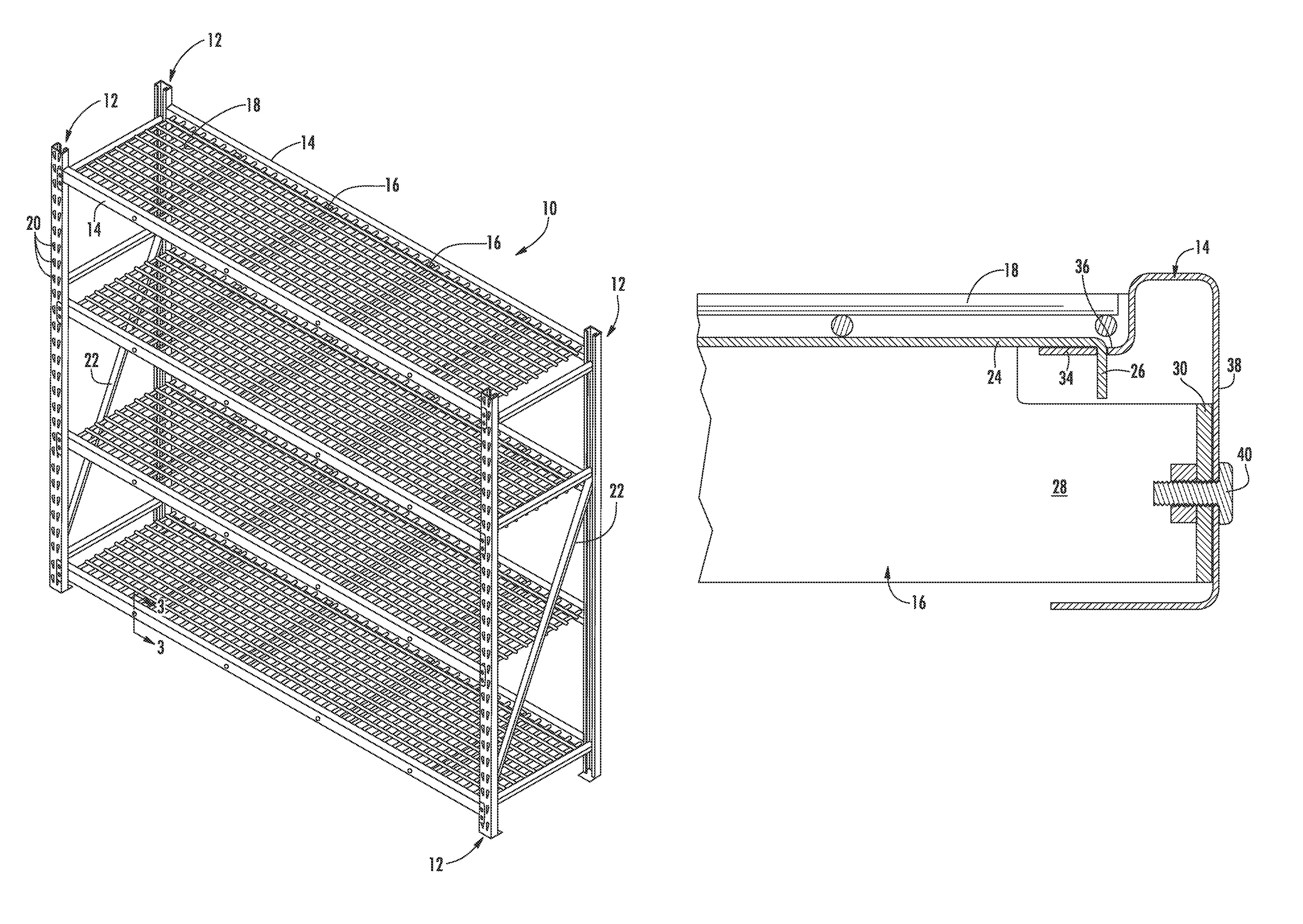
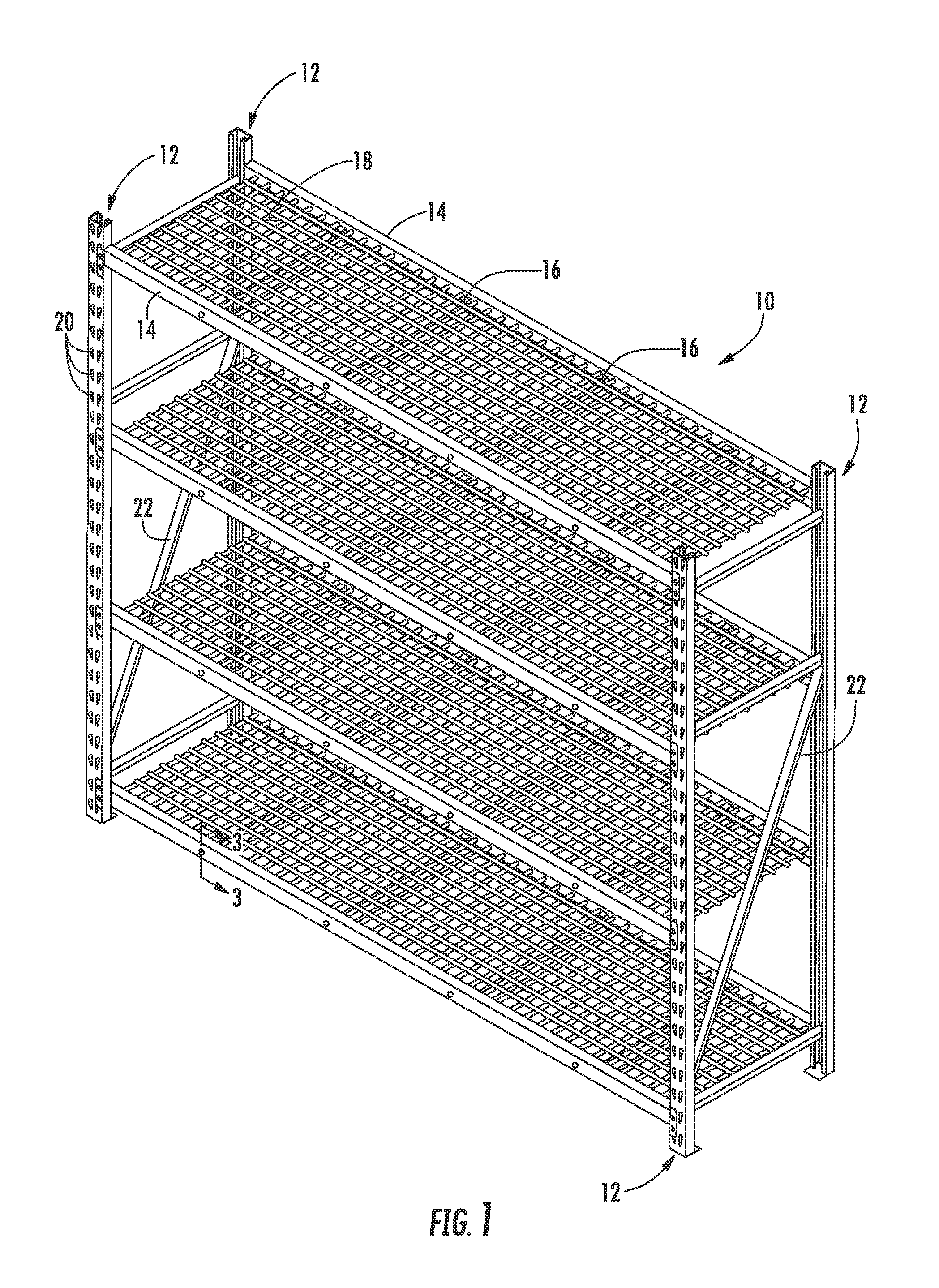
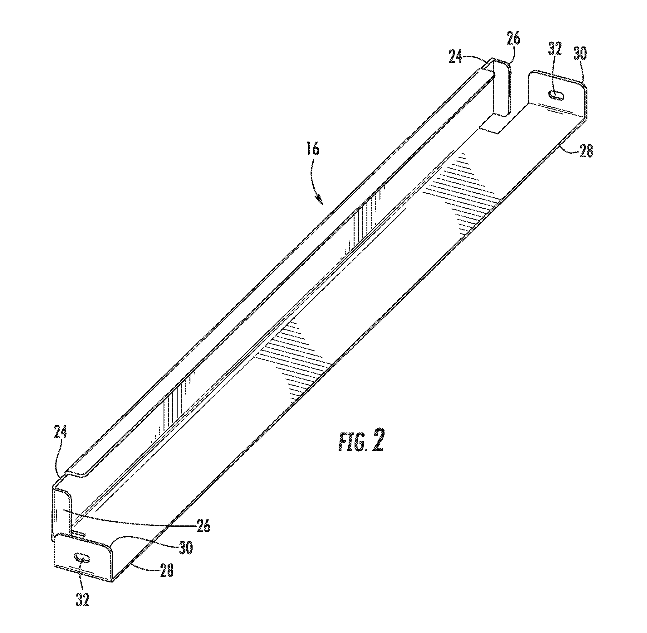
[0017]Now referring to the drawings, the improved shelf-type storage rack system is shown and generally illustrated in the figures. As can be seen the storage rack system includes an improved cross bar attachment that is used to create the framing for storage shelves. The cross bars of the present invention are locked or secured against undesired movement and rolling to create a shelf that properly supports loads Further, the locking cross bars are also readily removable and reusable.

[0018]As can be seen at FIG. 1, the shelf-type storage rack 10 of the present invention includes generally includes at least four vertical supports 12. The vertical supports 12 are generally arranged as a pair of rear vertical spaced supports and a pair of opposed, spaced front vertical supports. Each of the pairs of vertical supports is rigidly interconnected to one another by generally horizontal deck beams 14 that are positioned in a transverse relation between opposing pairs of the vertical support ...


PUM


Abstract

A storage rack system is provided that includes an improved cross bar attachment to create the framing for storage shelves. The cross bars are locked or secured against undesired movement and rolling to create a shelf that properly supports loads. The cross bars extend between the deck beams such that flanges at the ends thereof overlap the top of the deck beams. The flanges include a tab that extends downwardly to engage with an opening on the top of the deck beams. The lateral support further includes a stabilizer that is fastened to the side wall of the deck beams to prevent rolling or dislodgement of either member.

Description

BACKGROUND OF THE INVENTION[0001]The present invention relates generally to shelf-type storage rack systems. More particularly, the present invention relates to the support framing system and an improved cross bar attachment used to create the framing for storage shelves. The cross bars of the present invention are locked or secured against undesired movement and rolling to create a shelf that properly supports loads. Further, the locking cross bars are also readily removable and reusable.[0002]Shelf-type storage racks are widely known in the art. Various racking systems can be seen throughout the residential storage, retail sales and warehouse industry. Typical shelf-type storage racks include at least four vertical columns rigidly interconnected by generally horizontal deck beams which are positioned in a transverse relation between opposing pairs of columns. These columns are then spaced apart in a parallel relationship by cross bars and often diagonal members. Shelves are then s...

Claims


Application Information

Patent Timeline
Patent Type & Authority Patents(United States)
IPC IPC(8): A47B57/06A47B57/16A47B57/40
CPCA47B47/024A47B47/028
Inventor LAWSON, ALANPAINTER, STEVE
Owner LIVING STYLE B V I LTD
Why Eureka
Try Eureka