Method of installing geothermal heat pump system and device for installation

a geothermal heat pump and installation method technology, applied in the direction of lighting and heating apparatus, insulation, borehole/well accessories, etc., can solve the problems of high drilling cost, more likely to encounter bedrock, and high installation cost of earth loops, so as to reduce or eliminate drilling through bedrock, less excavation and surface disturbance, and the effect of reducing the cost of drilling

Active Publication Date: 2013-05-21
UNITED AIR TEMP HEATING & AIR CONDITIONING
View PDF7 Cites 2 Cited by
  • Summary
  • Abstract
  • Description
  • Claims
  • Application Information

AI Technical Summary

Benefits of technology

[0015]As compared to the conventional well (vertical) drilling method, the method of the present invention offers the advantage of reducing or eliminating drilling through the bedrock. Also, the problem of soil becoming more compact at depth, slowing drilling speed, is mitigated.
[0016]As compared with horizontal installation of earth loops, the method of the present invention requires far less excavation and surface disturbance and, therefore, incurs less cost.
[0017]Unlike the pull-through method, the method of the present invention requires no exit point and, therefore, requires less in property dimensions and provides a more efficient use of tubing in that a higher percentage of the earth loop is emplaced deeper than 3 feet and deeper than 8 feet. Further, a linear borehole on a slant has been found to enable a better, more complete grout fill between the tubing and the surrounding earth, i.e. a better seal and better heat exchange.

Problems solved by technology

A significant expense unique to the geothermal heat pump systems is the cost of installation of the earth loops.
However, this system requires removal of a considerable amount of earth and / or rock and results in disturbance of the land surface and possible damage to the landscape.
However, this approach, in many areas of the country, is more likely to encounter bedrock and a high drilling cost.
Even absent the problem of bedrock, i.e. in the coastal plain and river deltas, the earth becomes more compact with depth, resulting in higher drilling cost with increase in depth.
However, the dimensions of residential property often do not provide a length of property sufficient for proper spacing between the points of entry and exit.
Further, this pull-through installation necessarily uses a curved borehole which complicates filling with grout around the tubing to provide a good seal for heat exchange between the tubing and the earth.

Method used


Image

  • Method of installing geothermal heat pump system and device for installation
  • Method of installing geothermal heat pump system and device for installation
  • Method of installing geothermal heat pump system and device for installation

Examples


Embodiment Construction

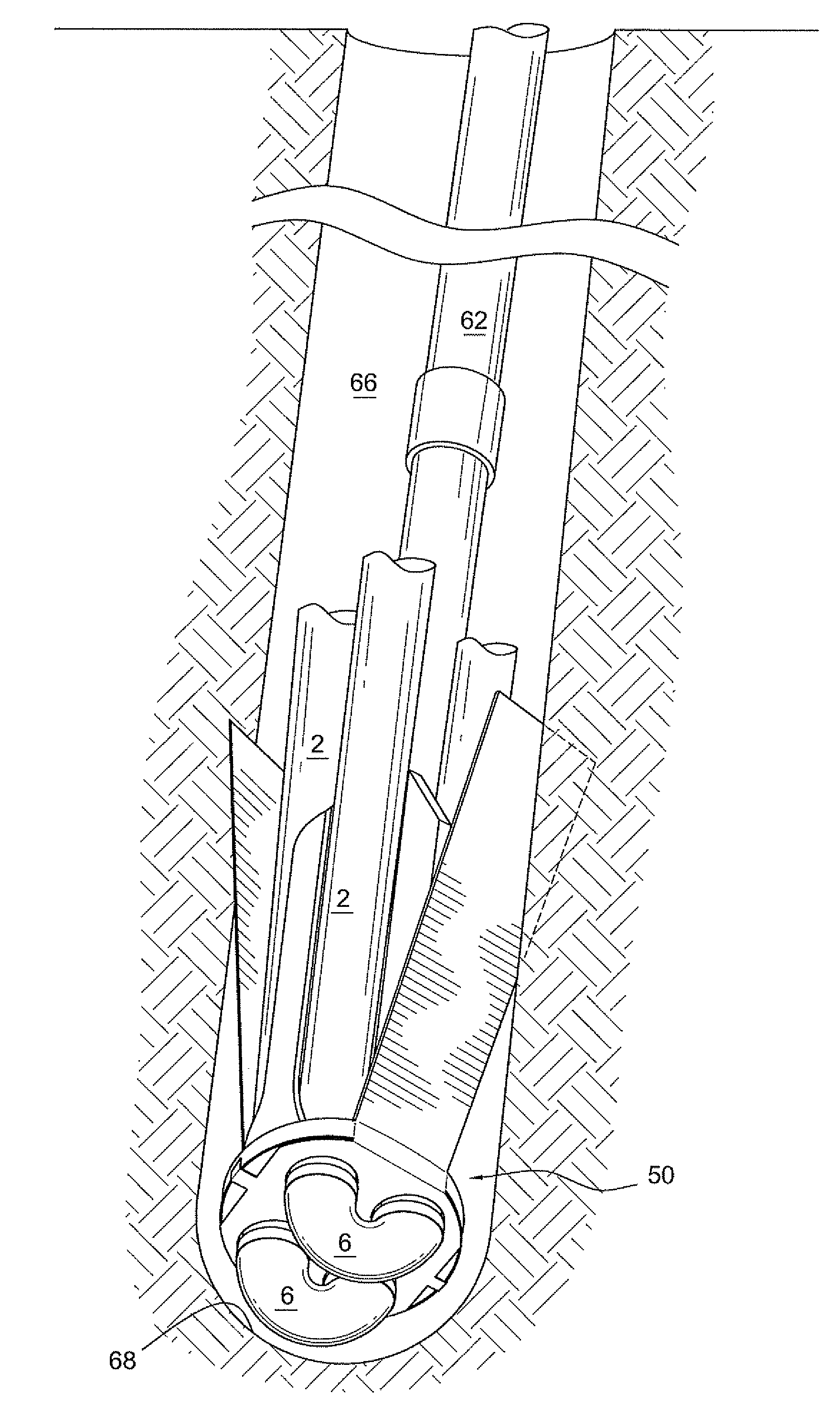
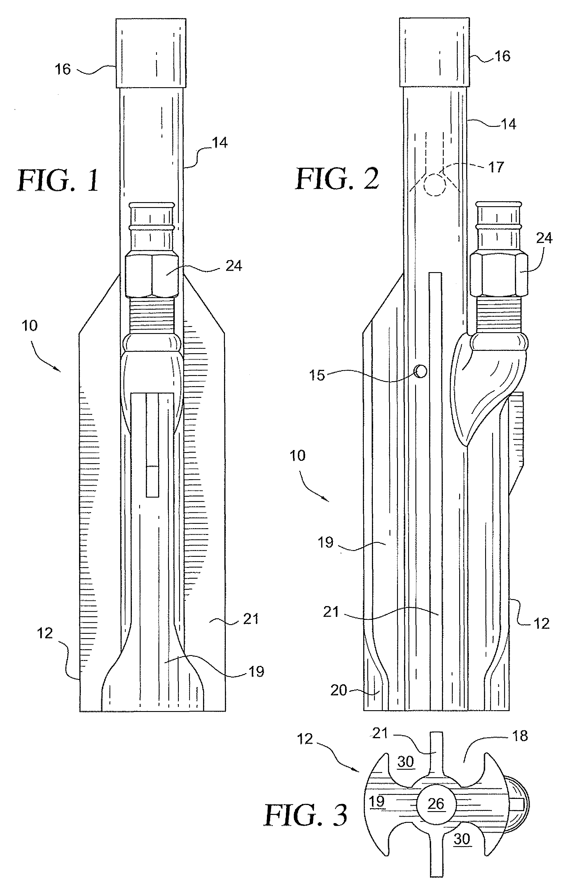
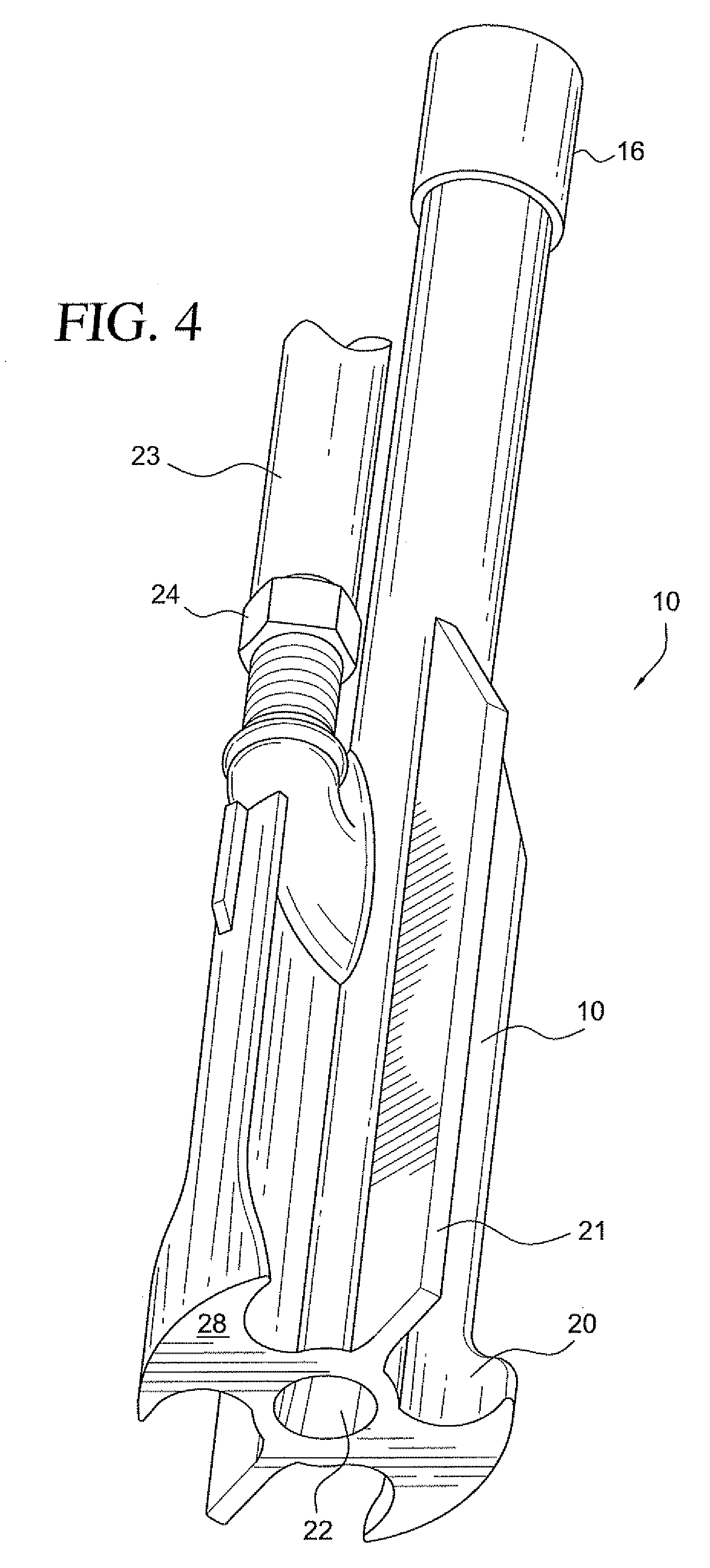
[0028]FIGS. 1-4 show the earth loop installation tool 10 as having a head portion 12 and a stem portion 14. The stem portion 14 may be simply a drill string section welded at one end to the rear end face of the tool 10, with a threaded fitting 16 at its free (“distal”) end. Running the length, or a major portion of the length, of the head 12 are four slots (“cylindrical recesses” or “scallops”) 18, sized to receive ¾ inch plastic tubes 2 as shown in FIG. 9. The recesses 18 are defined between large wings 19 and small wings 21. Of course, alternatively, the slots 18 could be sized to receive any diameter tubing. Tabs 20 serve to constrict the opening of the slots 18 to less than the diameter of the tubes and may be added to better hold the tubes 2 in place prior to placement of the anchor 40 over the tool 10. Due to their elasticity, the tubes 2 snap into place within the slots 18. A grout fitting 24 receives a grout mix through a grout hose, the grout passing through a central passa...


PUM


Abstract

An installation tool for installation of earth loops includes a cylindrical body with slots in its outer surface, for receiving of tubes of the earth loops, and a central passage extending therethrough from a grout fitting to a central opening at a leading end face of the cylindrical body. An anchor fits over the end face and includes a face plate with tube apertures extending therethrough, a retainer ring which serves to hold the earth loops in place within the slots during insertion of the tool into the borehole, and a pair of flexible plates extending from opposing positions on the retainer ring, approximately in parallel with the longitudinal axis of the cylindrical body. In use, a plurality of straight (linear) boreholes are drilled at an angle relative to the horizontal of 5° to less than 90°, preferably 5° to 45°, at least two coupled tube pairs are inserted into each borehole and then grout is injected to force the anchor away from the cylindrical body, to fill the boreholes surrounding the earth loops and to form a seal for heat exchange between the earth loops the surrounding earth.

Description

BACKGROUND OF THE INVENTION[0001]1. Field of the Invention[0002]The present invention relates to installation of heat exchange loops (“earth loops”) for a geothermal heat pump system and to a tool for use in the installation and to a compact geothermal heat pump system.[0003]2. The Prior Art[0004]In recent years, heat pumps have become widely used for both heating and cooling of residential and other buildings. Because of the numerous cost and environmental advantages they provide, heat pump systems have come to replace the traditional heating / cooling systems which employ the combination of a furnace, typically gas-fired or electric, and an air-conditioning system. More specifically, as compared to gas-fired (combustion) furnaces, in a heating mode, heat pump systems provide a more uniform temperature throughout a building, without a sudden blast of hot air on start-up and do not dry out the air as do the traditional furnaces, thus maintaining a higher humidity and a healthier indoo...

Claims


Application Information

Patent Timeline
Patent Type & Authority Patents(United States)
IPC IPC(8): E21B33/13
CPCE21B33/14F24J3/081F24J2003/088F28D20/0052Y02E10/12F24T10/10F24T2010/53Y02E10/10
Inventor TALKIN, LUKE
Owner UNITED AIR TEMP HEATING & AIR CONDITIONING
Why Eureka
Try Eureka