
Long T1 artifact suppression techniques for magnetic resonance imaging

a long-t1 artifact and magnetic resonance imaging technology, applied in the field of long-t1 artifact suppression techniques for magnetic resonance imaging, can solve the problems of preventing the identification of infarcted territory, affecting the detection accuracy of infarcted territory, etc., to achieve the maximum recovery of normal myocardium and suppress the signal from long-t1 species

Active Publication Date: 2013-05-21
DUKE UNIV +1
View PDF11 Cites 4 Cited by
  • Summary
  • Abstract
  • Description
  • Claims
  • Application Information

AI Technical Summary

Problems solved by technology

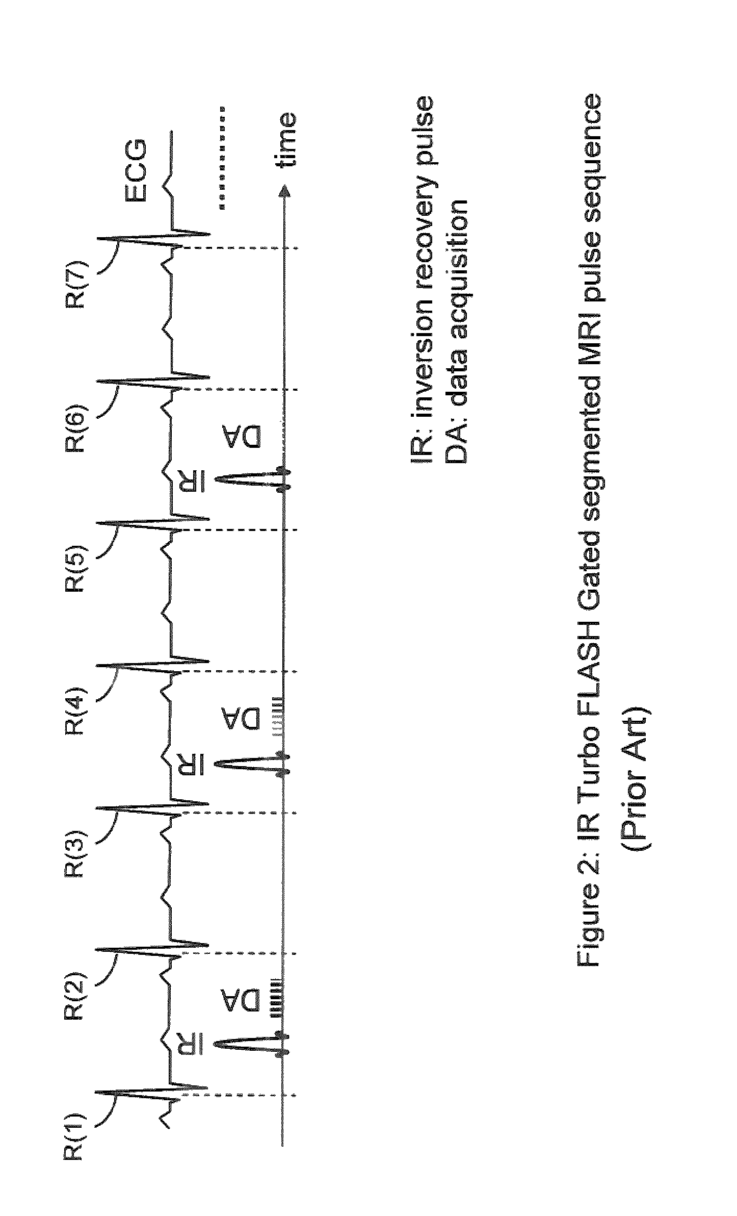
Myocardial delayed enhancement images acquired with segmented ECG-gated inversion recovery (IR)-prepared sequences often exhibit bright ghosting artifacts which impede the identification of infarcted territory.
Damage caused by a heart attack
Heart valve problems
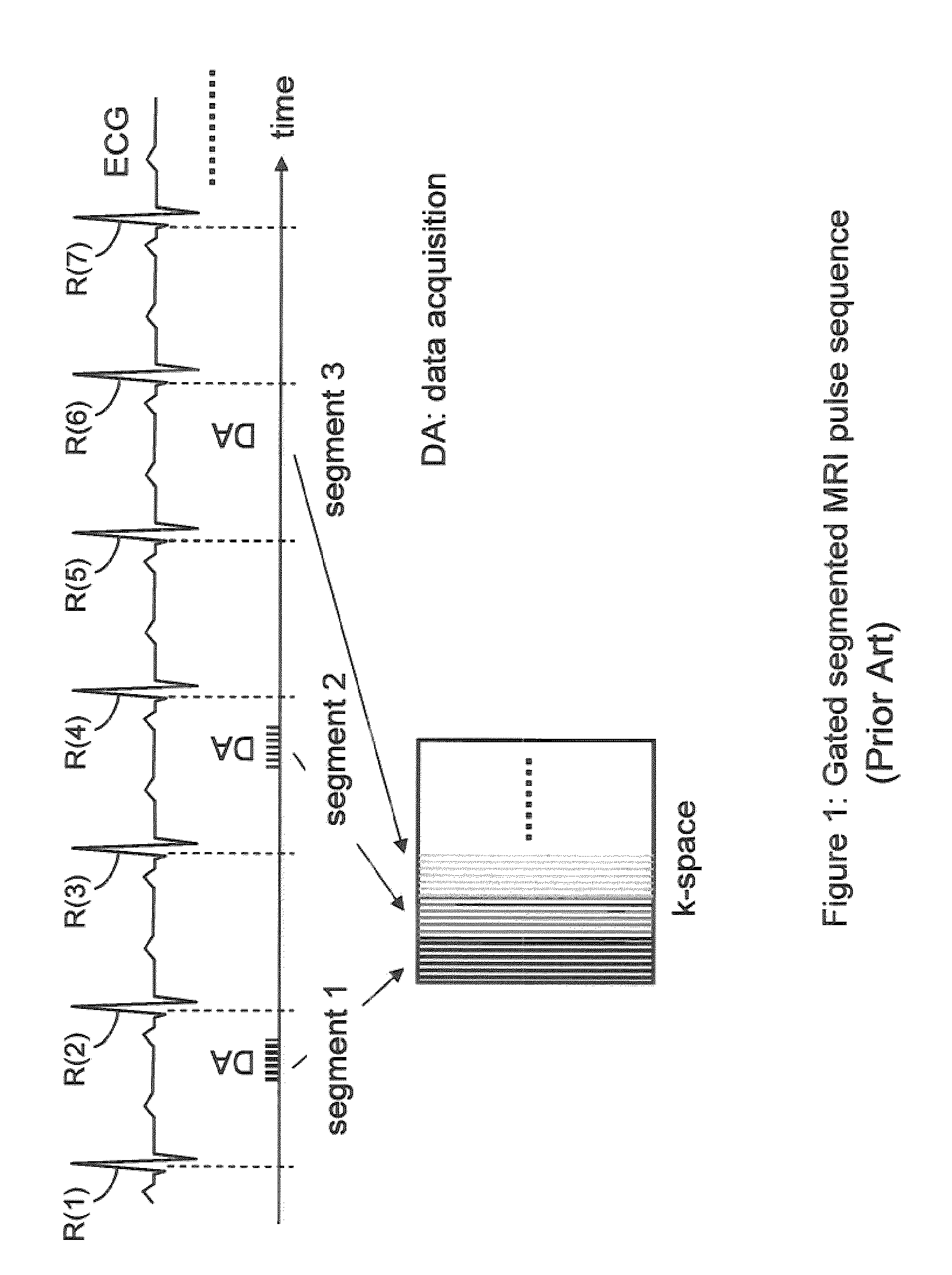
Natural motion and flow in the human body such as cardiac contraction and aortic blood flow generally occur too fast to be accurately captured within a single shot.
Since the patient is generally asked to hold her breath during the segmented data acquisition, there is a practical limit to the number of heartbeats in the data collection.
While this and other segmented sequences are now widely used, there can be some problems in certain applications such as cardiac and other imaging, as will now be explained.
Even then, matter with very long T1 may not be at steady state.
Image artifacts due to not being at steady state can occur in other sequences as well.
Even then, matter with very long T1 may not be at steady state.
Therefore, fluids with long T1 values called long-T1 species, including pericardial effusion, pleural effusion, CSF around the brain and spine, saline in breast implants, and stomach fluid, are prone to cause such artifacts even when dummy pulses are played.
Once again, the artifacts can occur if the longitudinal magnetization during data readout varies from one readout to the next.
Such ghosting image artifacts can hamper clinical image evaluation and sometimes prevent a clinical diagnosis based on the acquired MR images.
For example, a ghost from pleural effusion may be placed on top of the structure of interest such as a long axis view of the heart so that a diagnosis is not possible.
Even worse, they can also lead to a wrong diagnosis in for example delayed enhancement (myocardial viability) images.
This would lead to a false positive diagnosis and possibly inappropriate patient treatment.
This approach results in prolonged scan time.
Furthermore, this approach generally only weakens the intensity of the ghosting artifact but does not remove it completely.
The reason is that a single dummy period is not enough to drive the long-T1 species into steady state.
This approach works but is only possible if the long-T1 species is not part of the imaged structure.
Therefore, for example, this is not possible for pericardial effusion as the band would destroy the signal of the heart as the organ of interest.
Even in contexts (e.g., pleural effusion) where it is possible, this approach generally requires scanner operator skill and time to position the saturation slab and adjust its thickness.
Even then, the time point when the saturation pulse is played in the pulse sequence is not optimal and artifacts may still arise.

Method used


Image

  • Long T1 artifact suppression techniques for magnetic resonance imaging
  • Long T1 artifact suppression techniques for magnetic resonance imaging
  • Long T1 artifact suppression techniques for magnetic resonance imaging

Examples


embodiment

Saturation Prepulse Embodiment

[0109]While some exemplary illustrative non-limiting implementations use inversion or partial inversion pre-pulses followed by a time delay, saturation recovery prepulses or a combination of saturation and inversion pulses could be used. For example, another exemplary illustrative non-limiting implementation provides an artifact suppression module that consists of a saturation recovery (SR) pre-pulse preceded by a time delay dp (pre-delay) relative to the beginning of the period. See FIG. 9. The module is played in the period immediately before the regular imaging pulse sequence. Time delay dp is selected to be equal to di, where di is the time delay between the beginning of each acquisition period and the inversion recovery (IR) pulse. Delay dp can be also be chosen to be shorter than di, but must be larger positive. The exact value of di is a function of the pulse sequence parameters and the imaging period (e.g. the patient's RR interval). A precise c...

example

[0112]FIG. 11 shows an example non-limiting magnetic resonance imaging system 40 including a conventional magnet 69, RF transceiver 60, 62 and image reconstruction computer 50 which displays an image 59 on display 58. The exemplary illustrative non-limiting implementation has been programmed and successfully used on a Siemens Avanto (e.g., 1.5 Tesla) and a Siemens or Sonata scanner, but it can be implemented on any commercial cardiac or other MRI scanner irrespective of the manufacturer. No additional hardware is required, a software change (see block 52) suffices. The module could be integrated into portions of the software so that it can be played prior to all segmented inversion recovery sequences in the same way that the current dummy heart beats are used. The specified timing is applicable to MRI scanners with a 1.5 Tesla field strength, but it can be slightly modified to accommodate the 3 Tesla field strength scanners that are increasingly gaining in popularity. In fact the ex...


PUM


Abstract

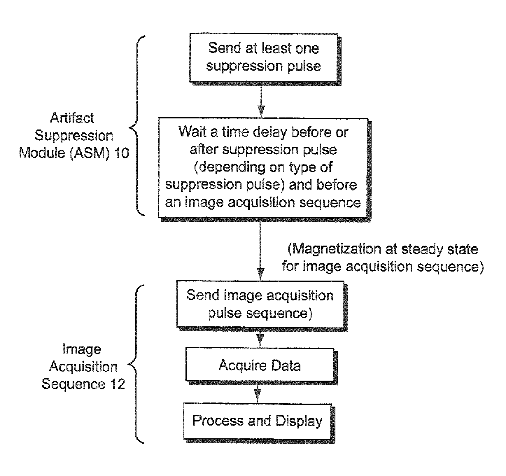
A method of suppressing artifacts arising from tissue, fluids, or other long-T1 species when acquiring magnetic resonance data with a segmented pulse sequence that assumes that magnetization is at steady state, said method including suppressing artifacts by producing an artifact suppression module (ASM) before the segmented sequence, the artifact suppression module comprising at least one selective, non-selective, or volume-selective suppression pulse and a time delay.

Description

CROSS-REFERENCES TO RELATED APPLICATIONS[0001]This application claims the benefit of priority from U.S. provisional application No. 61 / 092,881 filed Aug. 29, 2008.STATEMENT REGARDING FEDERALLY SPONSORED RESEARCH OR DEVELOPMENTField[0002]The technology herein relates to suppression of artifacts in Magnetic Resonance Imaging (MRI) and Nuclear Magnetic Resonance (NMR), and more specifically to suppressing artifacts in Magnetic Resonance Imaging (MRI) originating from fluids, tissues and other matter with long T1 values (“long-T1 species”) including but not limited to pericardial effusion, pleural effusion, cerebro-spinal fluid, saline breast implants and stomach fluid, when acquiring magnetic resonance data with a pulse sequence that assumes incorrectly that magnetization is at steady state. The technology herein more specifically relates to suppression of signal from long-T1 species by playing a non-selective saturation recovery (SR) or an inversion recovery (IR) prepulse and an assoc...

Claims


Application Information

Patent Timeline
Patent Type & Authority Patents(United States)
IPC IPC(8): G01V3/00
CPCG01R33/4818G01R33/5602G01R33/5613
Inventor REHWALD, WOLFGANG GERHARDCHEN, ENN-LINGKIM, RAYMOND J.
Owner DUKE UNIV
Learn More