
Integrated vehicle control system and apparatus

a vehicle control and integrated technology, applied in vehicle position/course/altitude control, process and machine control, instruments, etc., can solve problems such as failure of turn signal engagement, signal lights turning off prematurely, and problems that have existed

Active Publication Date: 2013-05-21
GOLOMB MERCANTILE COMPANY
View PDF16 Cites 24 Cited by
  • Summary
  • Abstract
  • Description
  • Claims
  • Application Information

AI Technical Summary

Benefits of technology

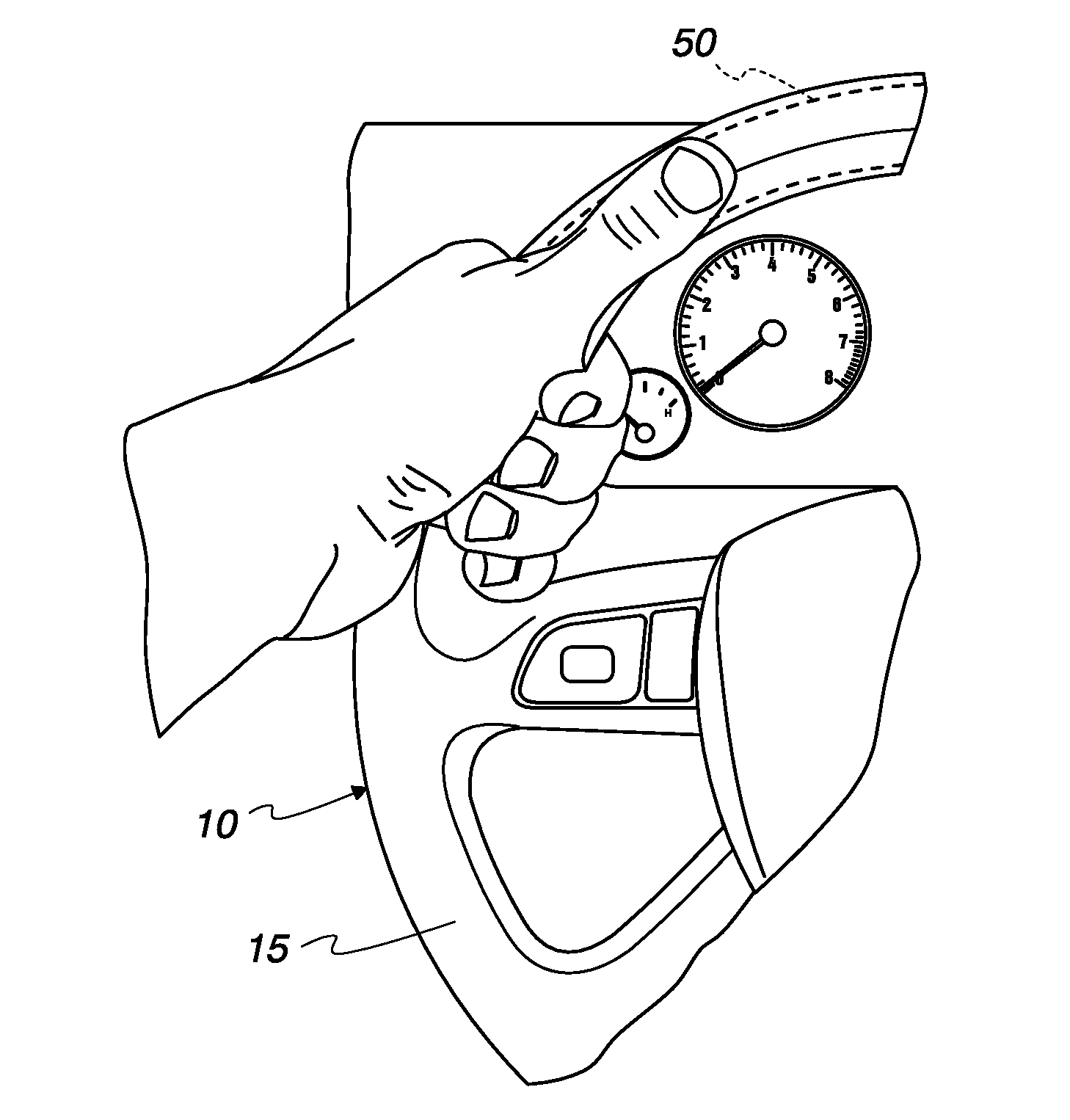
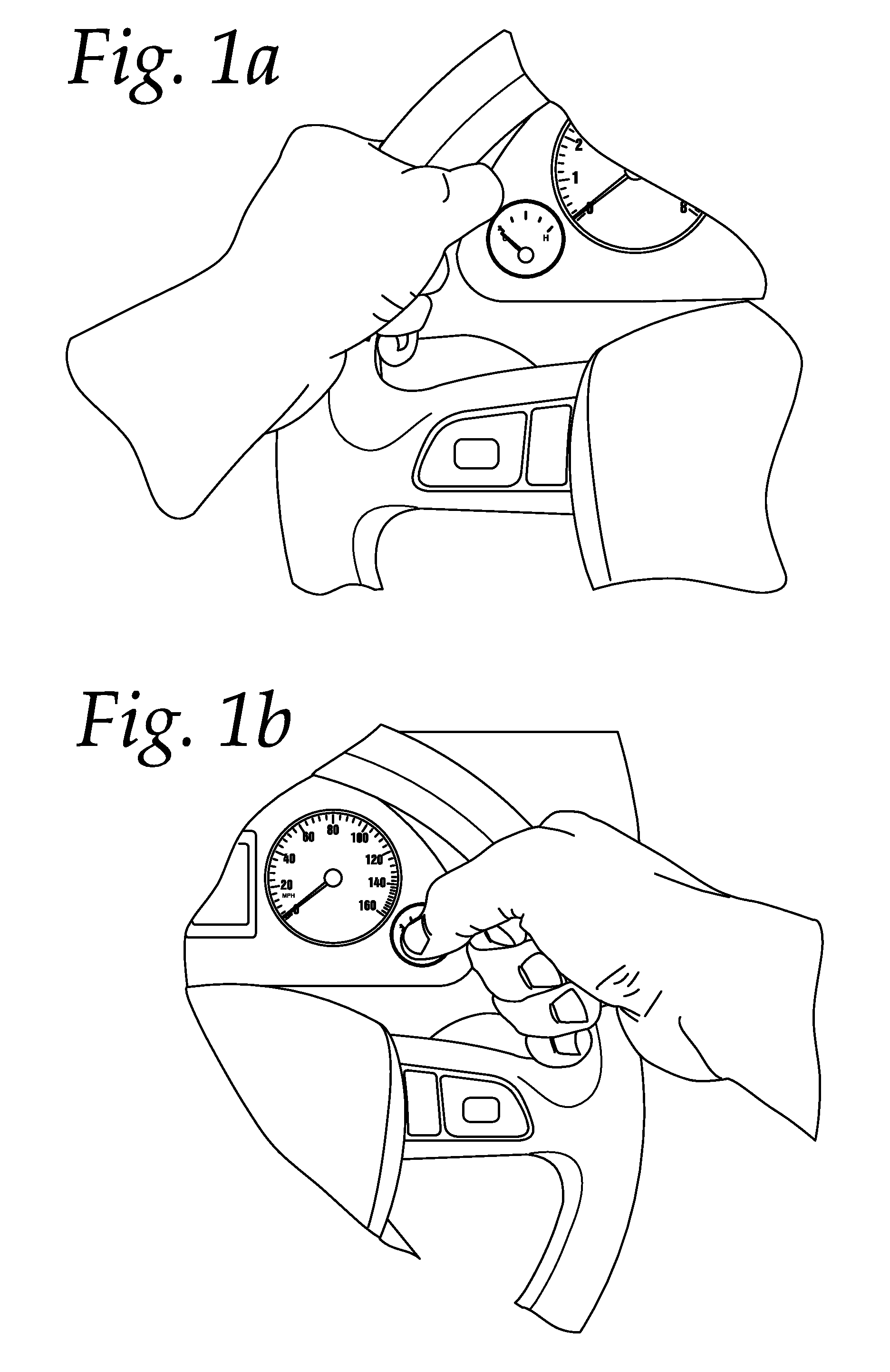
The present invention provides an activation switch and system that can be operated without a driver needing to change their grip on the steering wheel. This is particularly useful in high-risk or complex driving situations where the driver needs to shift gears while maintaining control of the steering wheel. The system includes an integrated thumb shifter system attached to the steering wheel's annular ring and connected to a controller that causes the motor vehicle's transmission to shift gears. The system can activate both the left and right actuators simultaneously to shift the transmission, and can also shift into the neutral or park position. Overall, the invention allows for safer and more intuitive driving experiences.

Problems solved by technology

With the mechanism described above, several well-known problems arise.
A common condition is that signal lights turn off prematurely if the steering wheel is momentarily turned even slightly away from the direction of the turn.
Another common condition is the failure of a turn signal to engage if the steering wheel is slightly turned in one direction and the driver attempts to signal a turn in the opposite direction.
Such problems have existed since the turn signal was first installed on a motor vehicle.
One disadvantage of this system is that one hand must be removed from the steering wheel in order to operate the stalk switch.
However, such modifications do not address the disadvantages described above.
Such modifications also do not address problems arising when the turn signal is left on after a turn or when the turn signal prematurely turns off.
Spoke-mounted turn signal activation switches, such as those envisioned in U.S. Pat. No. 5,823,666 to Kingsolver, do not eliminate the requirement that a driver's hand must be repositioned to activate the switch even if the hand remains in contact with the steering wheel.
As addressed above, such a design, like those placing the turn signal activation switch in the steering wheel hub, permits the operation of the switch without removing one hand from the steering wheel in very limited and still undesirable positions of the hand relative to the steering wheel.
Such a process of activating a turn signal, according to this publication, would not require a driver “to even move his or her hands much.” However, tests conducted demonstrated that the hot buttons of this hypothetical device cannot be pressed if the driver maintains a fully-wrapped four finger grip anywhere on the top half of the steering wheel.
Therefore, this hypothetical device suffers from all of the problems of other earlier devices because it merely relocates the functionality of the turn signal stalk switch to hot buttons on the rim of the steering wheel.
Turn signal lights may turn off prematurely if the steering wheel is momentarily turned even slightly away from the direction of the turn.
The computer-driver interfaces typically cannot be operated with the motor vehicle operator maintaining a fully wrapped grip around the annular ring of the steering wheel, and would require repositioning of the hands especially if the hands were originally positioned on the upper half of the steering wheel.
Some of the presently commercially available computer-driver interfaces have been criticized because their use requires a driver to look away from the road in order to locate and operate the interface.
It appears, however, that assignable / reassignable convenience keys are not available as integrated controls in the steering wheel of a motor vehicle.

Method used


Image

  • Integrated vehicle control system and apparatus
  • Integrated vehicle control system and apparatus
  • Integrated vehicle control system and apparatus

Examples


example 1

Activating Actuators 40, 50

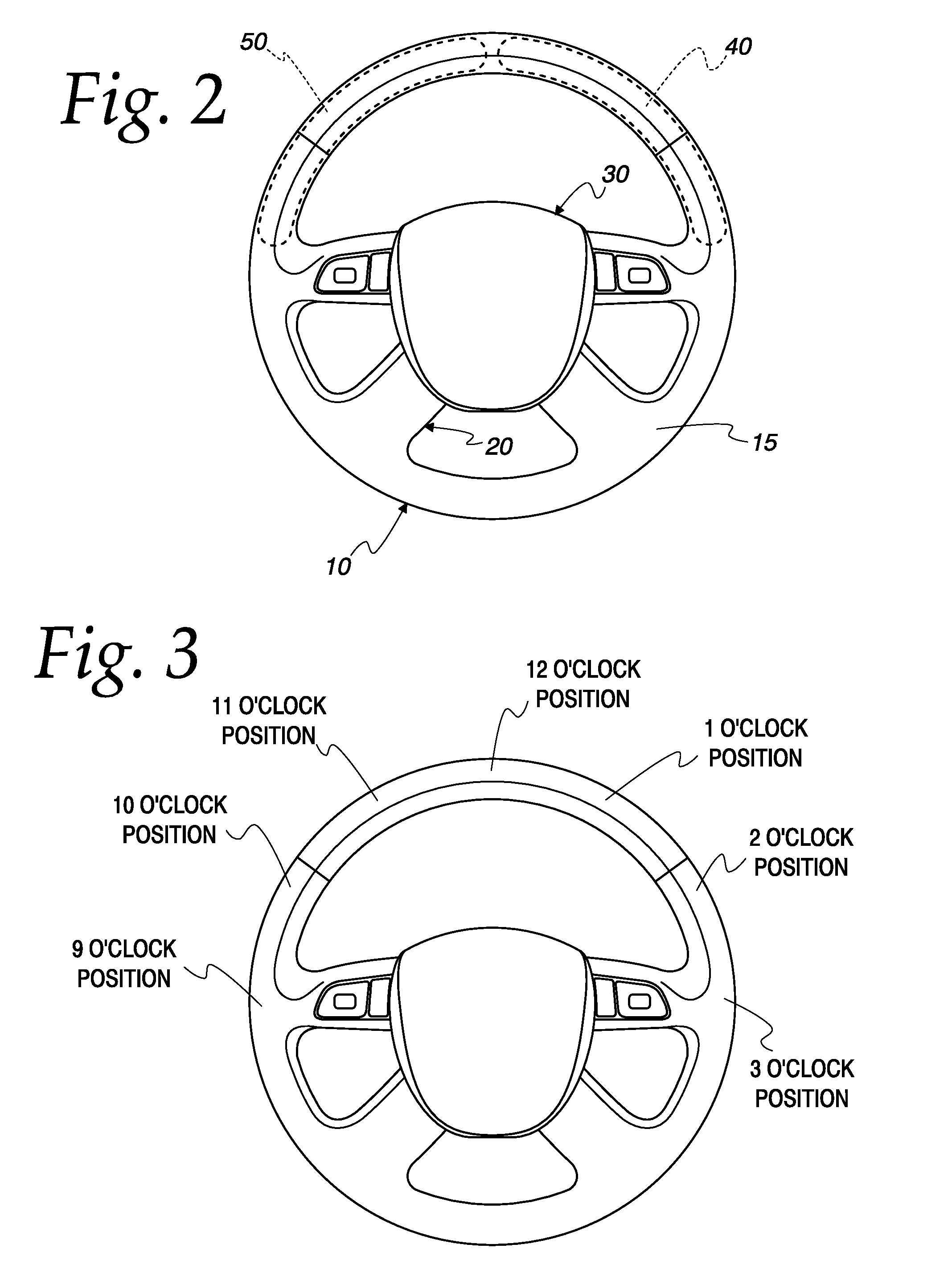
[0079]When a motor vehicle that has been modified to include the system and apparatus of the present invention, actuators 40, 50 may be activated when the motor vehicle's ignition (not shown) is turned on and the transmission 250 of the motor vehicle is in the neutral or park position. An operator of the motor vehicle may then activate actuators 40 and 50 by simultaneously depressing actuators 40 and 50 for a time that is within a pre-set threshold time range and further described herein above. Alternatively, when the motor vehicle's ignition is turned on and the motor vehicle is stopped (transmission 250 is in the drive position and the motor vehicle operator has engaged the motor vehicle's brake), simultaneously pressing actuators 40 and 50 immediately activates actuators 40 and 50. As further described above, once actuators 40 and 50 are activated, depressing actuator 40 will cause transmission 250 to be up shifted into gear, from park to first gear for...

example 2

Operating Actuators 40, 50

[0080]When a motor vehicle that has been modified to include the system and apparatus of the present invention, the following example illustrate adaptations of the present invention in which actuators 40 and 50 are activated and are subsequently being used as thumb shifters. In the present adaptation:[0081]1) depressing actuator 40 will cause transmission 250 to be upshifted (from first gear to second gear for example);[0082]2) depressing actuator 50 will cause transmission 250 to be downshifted (from second gear to first gear for example);[0083]3) depressing both actuators 40 and 50 for a first pre-set threshold duration or time range will cause transmission 250 to be shifted into the neutral position; and[0084]4) depressing both actuators 40 and 50 for a second pre-set threshold duration that is longer than the first pre-set threshold duration will turn off actuators 40 and 50.

example 3

Operating Actuators 40, 50—Further Adaptations

[0085]When a motor vehicle that has been modified to include the system and apparatus of the present invention, the following examples illustrate adaptations of the present invention in which the motor vehicle's ignition (not shown) is turned on, and actuators 40 and 50 are activated and are subsequently being used as thumb shifters to place the motor vehicle's transmission 250 into the neutral or park position. In the present adaptation:[0086]1) depressing both actuators 40 and 50, simultaneously, for a first pre-set threshold time range or duration will cause transmission 250 to be placed in the neutral position;[0087]2) continuing to depress actuators 40, 50, simultaneously for a second pre-set threshold duration that is longer than the first pre-set threshold duration will cause transmission 250 to be placed in the park position (the park position of transmission 250 cannot be accessed at any time the motor vehicle is not at a comple...


PUM


Abstract

The present invention provides a system which integrates motor vehicle component operation into actuators located in the rim of a motor vehicle steering wheel. The two actuators of the system of the present invention are located in an arc segment of the steering wheel defined by the three o'clock and 12 o'clock positions for the right-hand actuator and the nine o'clock and 12 o'clock positions for the left-hand actuator. The actuators may operate in parallel with a conventional stalk switch or controls associated with an on board computer and only operate a motor vehicle component when activated and subsequently depressed. The integrated vehicle control system and apparatus of the present invention further provides for vehicle component operation which does not require a driver to remove his or her hands from the steering wheel.

Description

CROSS REFERENCE TO RELATED APPLICATION[0001]This application is a continuation in part of U.S. Non Provisional Application Ser. No. 12 / 555,477, filed on Sep. 8, 2009, and is incorporated herein by reference to the extent allowed by law.FIELD OF THE INVENTION[0002]The present invention relates to a vehicle control system and apparatus for operating the vehicle's components that is integrated into the rim of a vehicle's steering wheel in such a way as to be fully operable without a driver of the vehicle being required to remove his / her hands from the steering wheel.BACKGROUND OF THE INVENTION[0003]Vehicle turn signals, while having been in use on commercially available motor vehicles for about 70 years, have changed little since their first application. More recently, vehicles have been equipped with computer-operated functionality which allows the vehicle's driver or operator to control the vehicle's radio, compact disc player, connected devices, cellular telephone and navigation sys...

Claims


Application Information

Patent Timeline
Patent Type & Authority Patents(United States)
IPC IPC(8): B60Q1/00
CPCB60Q1/0082B62D1/046B60Q1/343Y10T74/20834
Inventor GOLOMB, ADAM SIMON
Owner GOLOMB MERCANTILE COMPANY
Learn More