Catenary cable solar panel suspension system

a solar panel and catenary cable technology, applied in the direction of heat collector mounting/support, pv power plants, lighting and heating equipment, etc., can solve the problems of high cost, large ground connection of mount systems, and inability to move without great difficulty and expense to the owner, and achieve the effect of preventing a catastrophic motion of the panels and high wind condition

Active Publication Date: 2013-05-28
OLYMPIC ENERGY SYST
View PDF22 Cites 32 Cited by
  • Summary
  • Abstract
  • Description
  • Claims
  • Application Information

AI Technical Summary

Benefits of technology

[0011]A level of tension in the first pair of cables acting in coordination with a level of tension in the second pair of cables ...

Problems solved by technology

As a result, typical ground mount systems are cost-prohibitive relative to existing costs for grid-supplied electrical energy.
These over-engineered systems are also...

Method used


Image

  • Catenary cable solar panel suspension system
  • Catenary cable solar panel suspension system
  • Catenary cable solar panel suspension system

Examples


Embodiment Construction

[0027]The following detailed description illustrates the invention by way of example, not by way of limitation of the scope, equivalents or principles of the invention. This description will clearly enable one skilled in the art to make and use the invention, and describes several embodiments, adaptations, variations, alternatives and uses of the invention.

[0028]In this regard, the invention is illustrated in the several figures, and is of sufficient complexity that the many parts, interrelationships, and sub-combinations thereof simply cannot be fully illustrated in a single patent-type drawing. For clarity and conciseness, several of the diagrams show in schematic, or omit, parts that are not essential in that diagram to a description of a particular feature, aspect or principle of the invention being disclosed. Thus, the best mode embodiment of one feature may be shown in one diagram, and the best mode of another feature will be called out in another diagram.

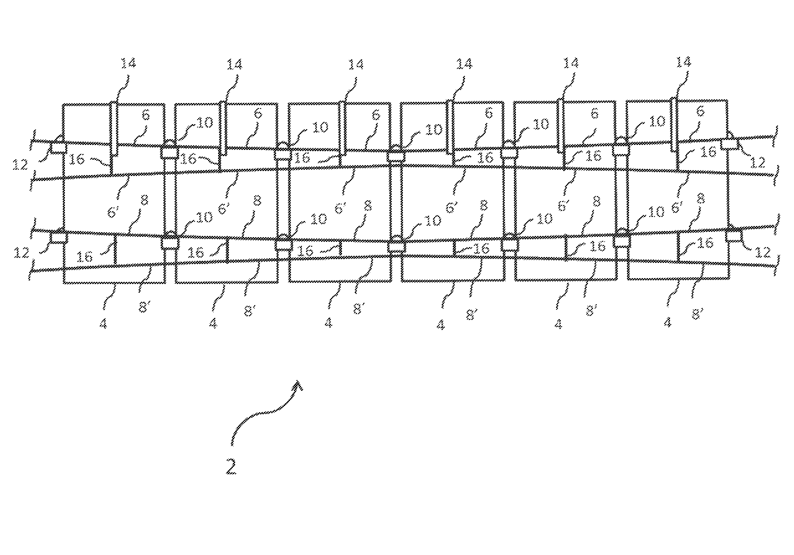
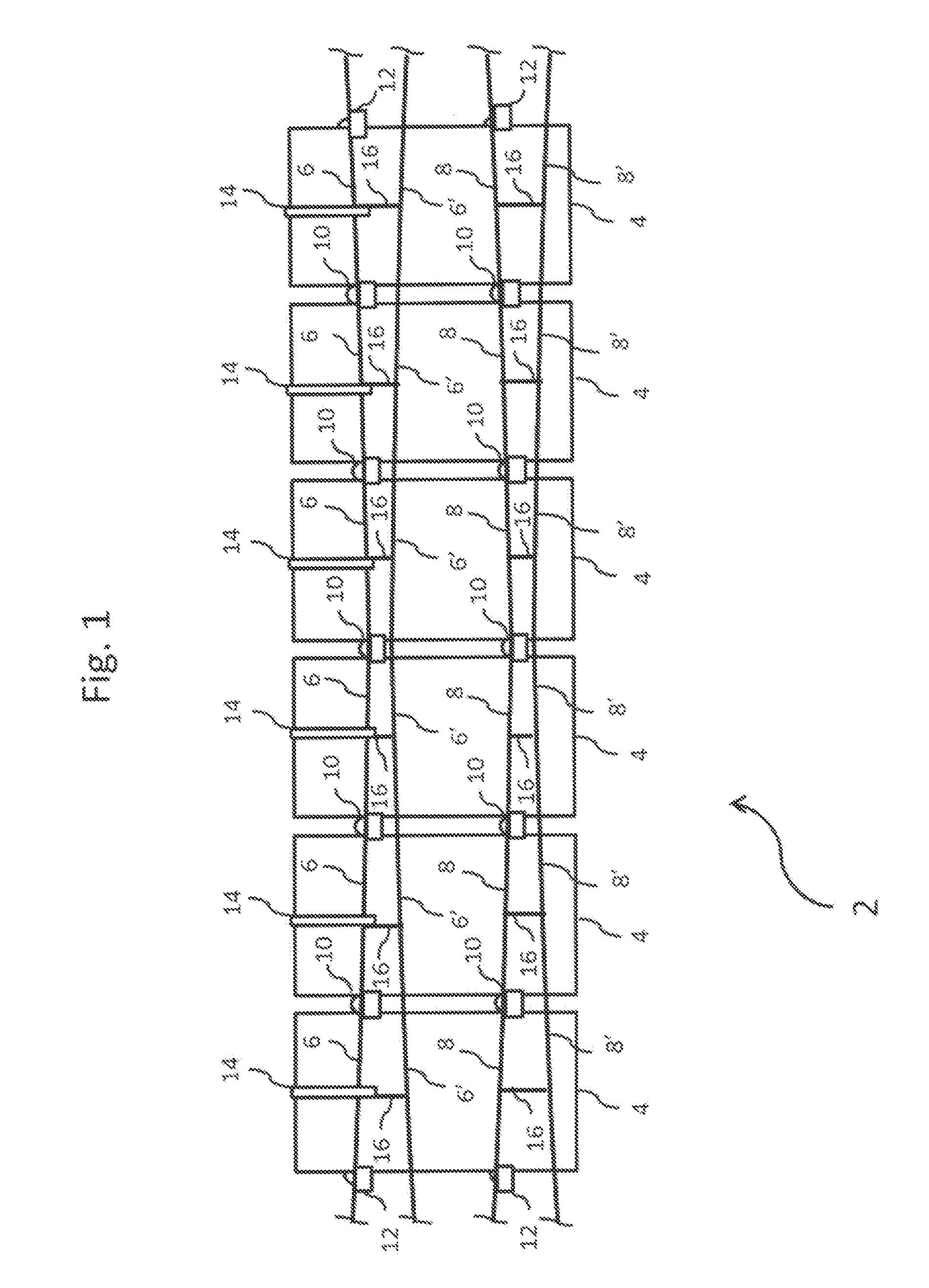
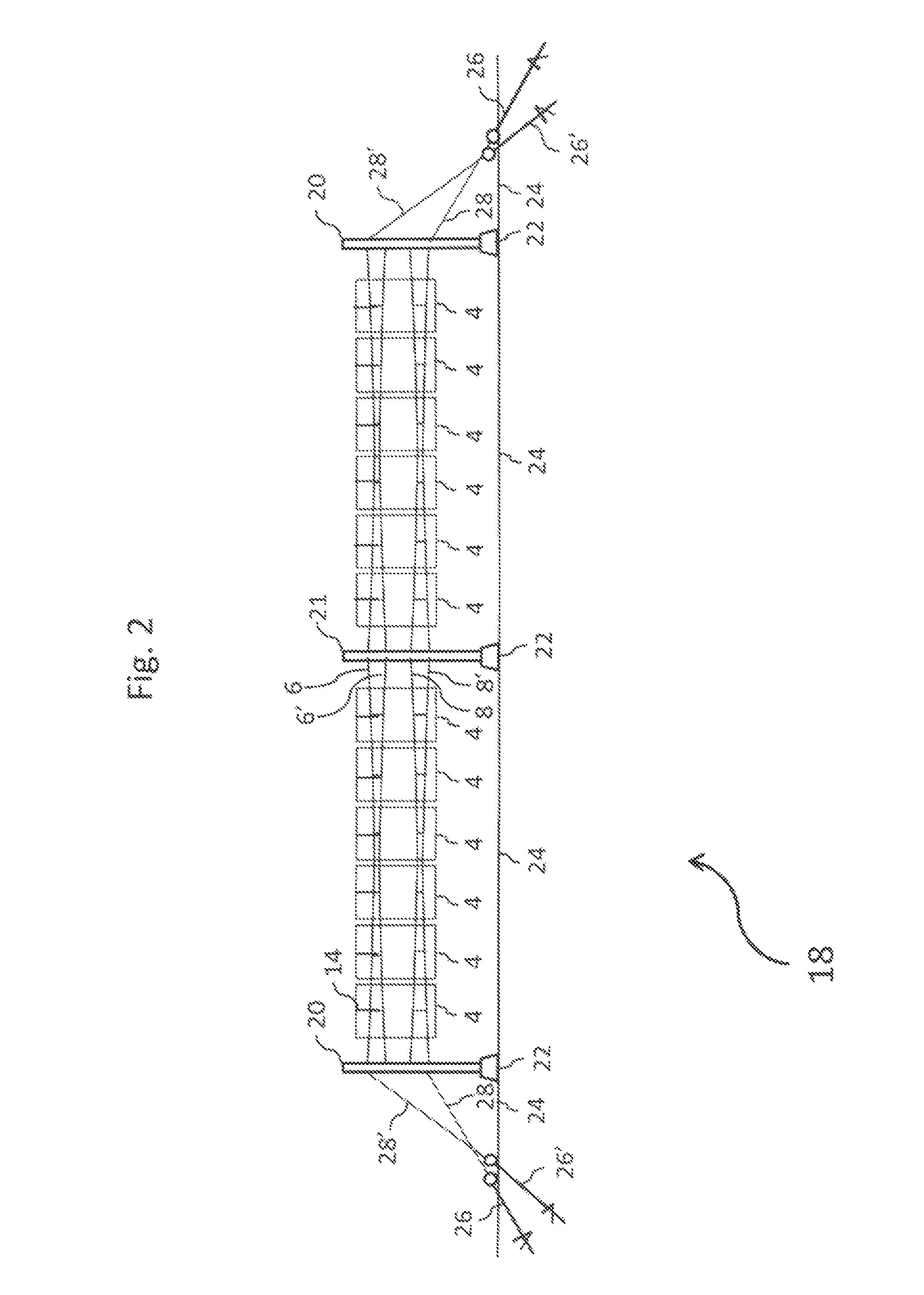
[0029]Catenary Cable ...


PUM


Abstract

A system of suspended photovoltaic modules relative to a surface wherein modules are suspended generally parallel and spaced apart along the length of dual pairs of catenary cables. A hanger assembly permits initial attachment of a module during installation as the cables are mounted to the rear surfaces of the modules via mid clamp assemblies. End clamp assemblies attach the modules to the cables proximate stanchions having two spaced posts joined by cross beams, a top cross beam angled to define an inclined plane. The respective pairs of cables supporting the modules are joined with cable cross ties to form a catenary shape. The modules may be suspended in a generally consistent inclined plane or a slightly concave curve. The catenary cables and clips are sized and shaped to allow the modules limited sway movement as necessary to reduce stresses and forces during wind or other adverse weather events.

Description

CROSS REFERENCE TO RELATED APPLICATION[0001]This application claims priority under 35 USC 119(e) of U.S. Provisional Patent Application Ser. No. 61 / 452,832 filed Mar. 15, 2011, entitled “Dual Opposing Catenary Solar Panel Mounting System” by the same inventor, hereby incorporated by reference in its entirety.FIELD OF THE INVENTION[0002]This invention relates generally to the mounting and securing of solar energy collectors such as photovoltaic panels, and more particularly to an above surface / ground mounting system that suspends panels via dual pairs of cables under tension forming a general catenary shape.BACKGROUND OF THE INVENTION[0003]Typical solar panel ground mounting systems require extensive infrastructure to support and position the panels laterally to form a consistent angle above the ground. Each panel must be supported along the length of the array. To support the panels in this perfectly planar, above-ground position, typical ground mount systems require days of labor a...

Claims


Application Information

Patent Timeline
IPC IPC(8): E04D13/18F24J2/52
CPCF24J2/5258F24J2/523F24J2/5241Y02B10/14Y02B10/20Y02B10/12Y02E10/47F24S25/10F24S25/50F24S25/636H02S20/10Y02B10/10Y02E10/50
Inventor CLEMENS, JONATHAN A.
Owner OLYMPIC ENERGY SYST
Why Eureka
Try Eureka