
Method for the assembly of a cap with a receptacle

a technology of receptacles and caps, which is applied in the direction of blood sampling devices, bottling operations, and closure lids, etc., can solve the problems of inability to access the interior, inability to separate media, and difficulty in putting the separation device in the interior of the housing container subsequently

Active Publication Date: 2013-05-28
GREINER BIO ONE GMBH
View PDF50 Cites 9 Cited by
  • Summary
  • Abstract
  • Description
  • Claims
  • Application Information

AI Technical Summary

Benefits of technology

The invention is about a method of assembling a cap with one end of a housing container, which is simple and inexpensive. This method can join components together without the need for automatic fitting machines and reduces the cost of maintenance work and repairs. The joined components can also be easily detached for further use if needed. Overall, this method simplifies the process of joining container systems and makes it easier to achieve the separation of mixed elements throughout the filling process. Additionally, the invention provides a housing container that is easier to use with a separating device, making the filling process easier and allowing for better separation of the mixed elements.

Problems solved by technology

The individual components are assembled and in particular the separating device is inserted in a vacuum chamber because once the separating device has been fitted, it is no longer possible to access the interior without damaging the latter.
The disadvantage of this design is that it is necessary to manufacture a tube with an internally lying stop and the function whereby the media are separated is not reliable due to the orifice provided in the separating device.
Furthermore, it is quite difficult to insert the separating device in the interior of the housing container subsequently.
The disadvantage of this approach is that the shelf life is not enough for standard applications in many cases due to the fact that the separating device is provided in the form of a gel.
As a result, this obviates the need for automatic fitting machines which have otherwise been required in the past to carry out the requisite rotating or pivoting movements.
This largely prevents adhesion and as a result distortion to the subsequent analysis process.
Furthermore, because the shoulder of the sealing device extends out from the external cap casing, the container system as a whole is not able to roll off a flat support surface, for example, when being used in its intended application.

Method used


Image

  • Method for the assembly of a cap with a receptacle
  • Method for the assembly of a cap with a receptacle
  • Method for the assembly of a cap with a receptacle

Examples


Embodiment Construction

[0112]Firstly, it should be pointed out that the same parts described in the different embodiments are denoted by the same reference numbers and the same component names and the disclosures made throughout the description can be transposed in terms of meaning to same parts bearing the same reference numbers or same component names. Furthermore, the positions chosen for the purposes of the description, such as top, bottom, side, etc., relate to the drawing specifically being described and can be transposed in terms of meaning to a new position when another position is being described. Individual features or combinations of features from the different embodiments illustrated and described may be construed as independent inventive solutions or solutions proposed by the invention in their own right.

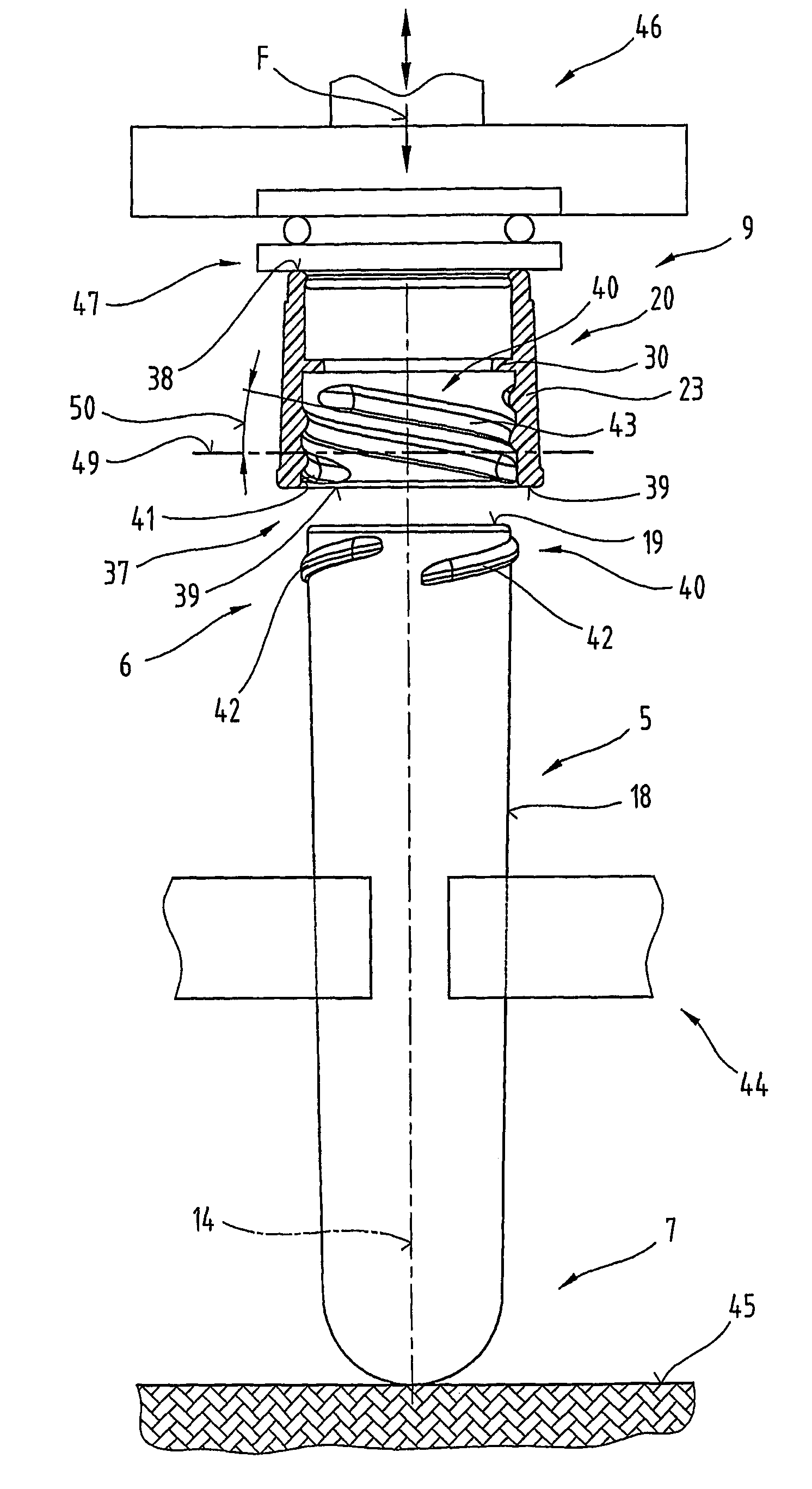
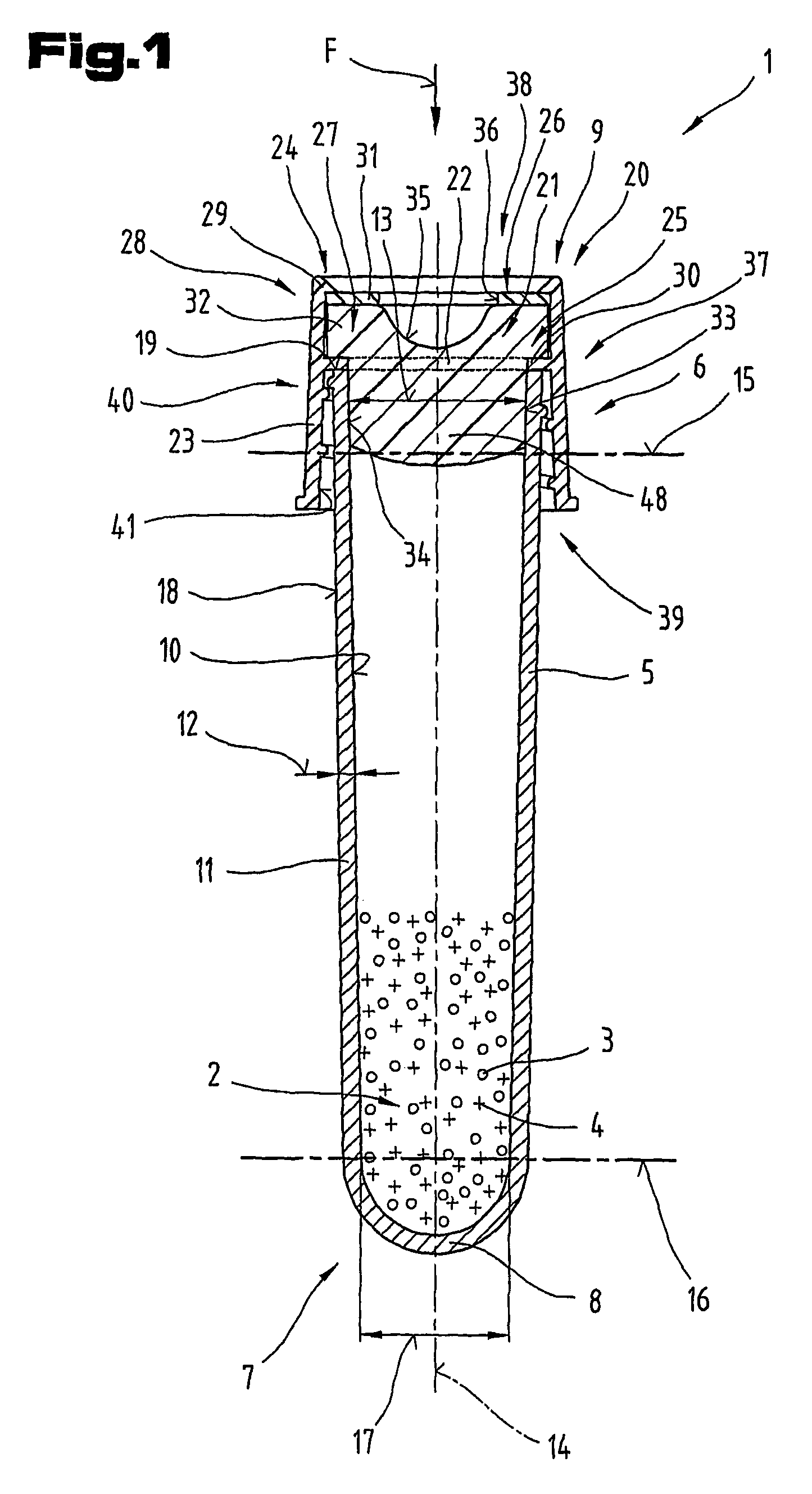
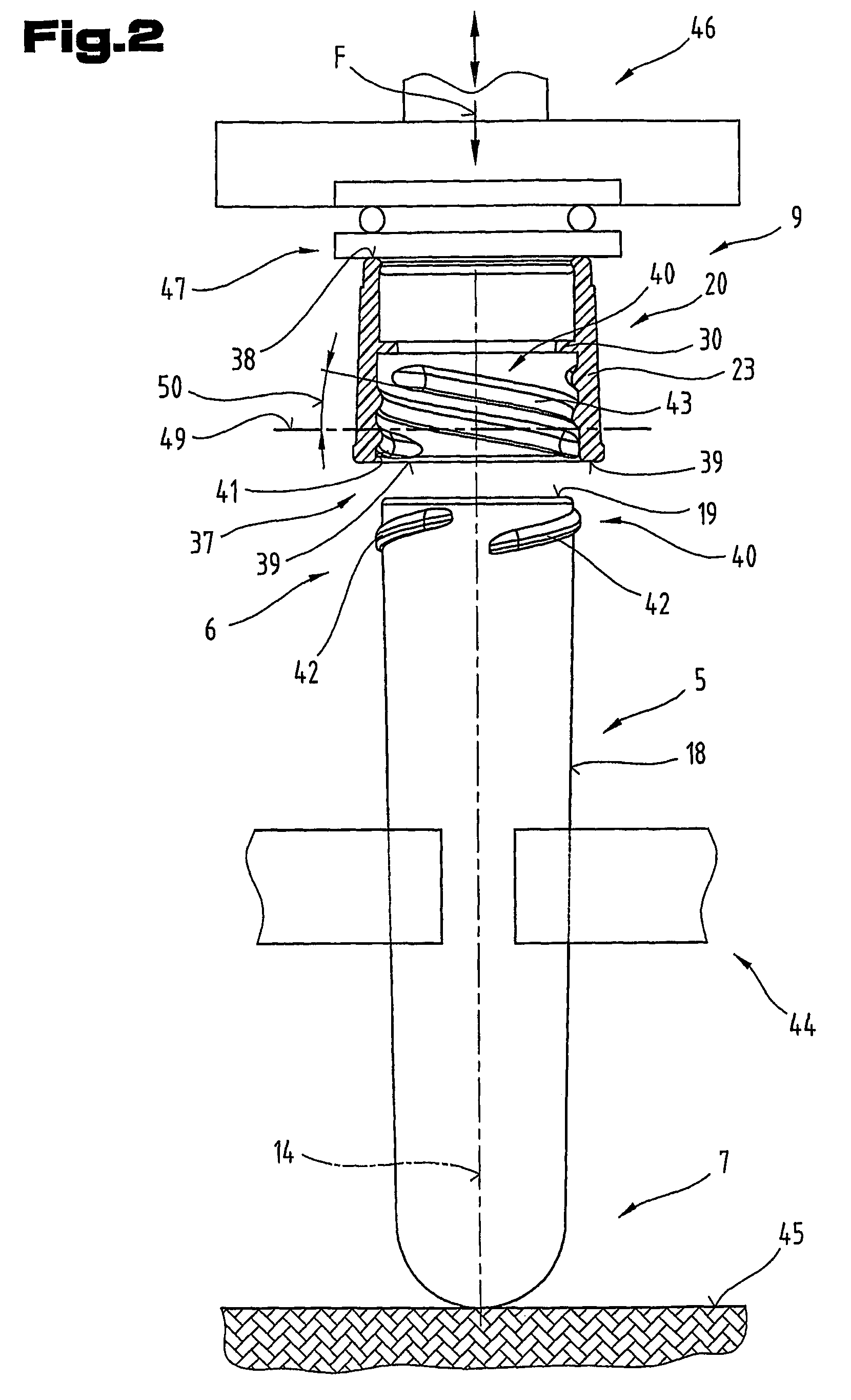
[0113]FIGS. 1 to 9 illustrate a container system 1, e.g. for a mixture 2 of at least two different constituents or media 3, 4, such as body fluids, tissue parts or tissue cultures, for exampl...


PUM


Abstract

The invention relates to a method of assembling a cap (20) of a closure device (9) with an open end (6, 7) of a housing container (5) for forming a container system (1) for body fluids, tissue parts or tissue cultures, whereby a relative rotating or pivoting movement is effected between the cap (20) and the housing container (5) about a common longitudinal axis (14). In order to generate the relative movement, a pressing force (F) is applied to at least one of the components to be assembled directed more or less in the direction of the longitudinal axis (14). The invention further relates to a cap (20) for forming the closure device (9), a housing container (5) and a container system (1) obtained as a result, comprising at least the cap (20), a sealing device (21) device retained in it and the housing container (5).

Description

CROSS REFERENCE TO RELATED APPLICATIONS[0001]Applicant claims priority under 35 U.S.C. §119 of Austrian Application No. A80 / 2004 filed Jan. 23, 2004. Applicant also claims priority under 35 U.S.C. §365 of PCT / AT2005 / 000004 filed Jan. 14, 2005. The international application under PCT article 21(2) was not published in English.BACKGROUND OF THE INVENTION[0002]The invention relates to a method of assembling a cap with one end of a housing container, a cap designed for this method, as well as a housing container and a resultant container system, of the type described as an example of the invention. The invention further relates to a housing container for inserting a separating device in its interior, of the type described as an example of the invention.[0003]Various container systems comprising a housing container and a closure device which can be coupled with it are described in patent specifications EP 0 867 378 A2, EP 1 174 084 B1, EP 1 174 085 B1 and U.S. Pat. No. 6,017,317 A1. In t...

Claims


Application Information

Patent Timeline
IPC IPC(8): B67B1/06B65D41/34B65D41/00B65D43/20B65D53/00B65D43/12B65D41/36B65D41/06B65D41/04B67B3/20B65B7/28B65B51/08A61B5/15A61J1/05B01L3/14B65D8/02B65D41/08B65D51/00B65D85/00C12M3/00
CPCB01L3/50825B65D51/002B01L2200/12B01L2300/042B65D51/00B65D41/08A61J1/05
Inventor KONRAD, FRANZ
Owner GREINER BIO ONE GMBH
Learn More