Bone growth device and method

a bone growth and bone technology, applied in the field of bone growth devices, can solve the problems of unwieldy external fixators for patients, two segments will completely fuse to each other, and the distraction period is compl

Active Publication Date: 2013-05-28
NUVASIVE SPECIALIZED ORTHOPEDICS INC
View PDF113 Cites 55 Cited by
  • Summary
  • Abstract
  • Description
  • Claims
  • Application Information

AI Technical Summary

Problems solved by technology

If the distraction rate is too high, there is a risk of nonunion, if the rate is too low, there is a risk that the two segments will completely fuse to each other before the distraction period is complete.
Distraction osteogenesis using external fixators has been done for many years, but the external fixator can be unwieldy for the patient.
It can also be painful, and the patient is subject to the risk of pin track infections, joint stiffness, loss of appetite, depression, cartilage damage and other side effects.
Having the external fixator in place also delays the beginning of rehabilitation.
This can sometimes be painful to the patient, and can often proceed in an uncontrolled fashion.
This therefore makes it difficult to follow the strict daily or weekly lengthening regime that avoids nonunion (if too fast) or early consolidation (if too slow).
The motorized intramedullary nails have an antenna which needs to be implanted subcutaneously, thus complicating the surgical procedure, and making it more invasive.
These devices are therefore designed to be lengthened in a controlled manner, but due to their complexity, may not be manufacturable as an affordable product.
Because of the complexity and size of the external stator, this technology has not been reduced to a simple and cost-effective device that can be taken home, to allow patients to do daily lengthenings.

Method used


Image

  • Bone growth device and method
  • Bone growth device and method
  • Bone growth device and method

Examples


Embodiment Construction

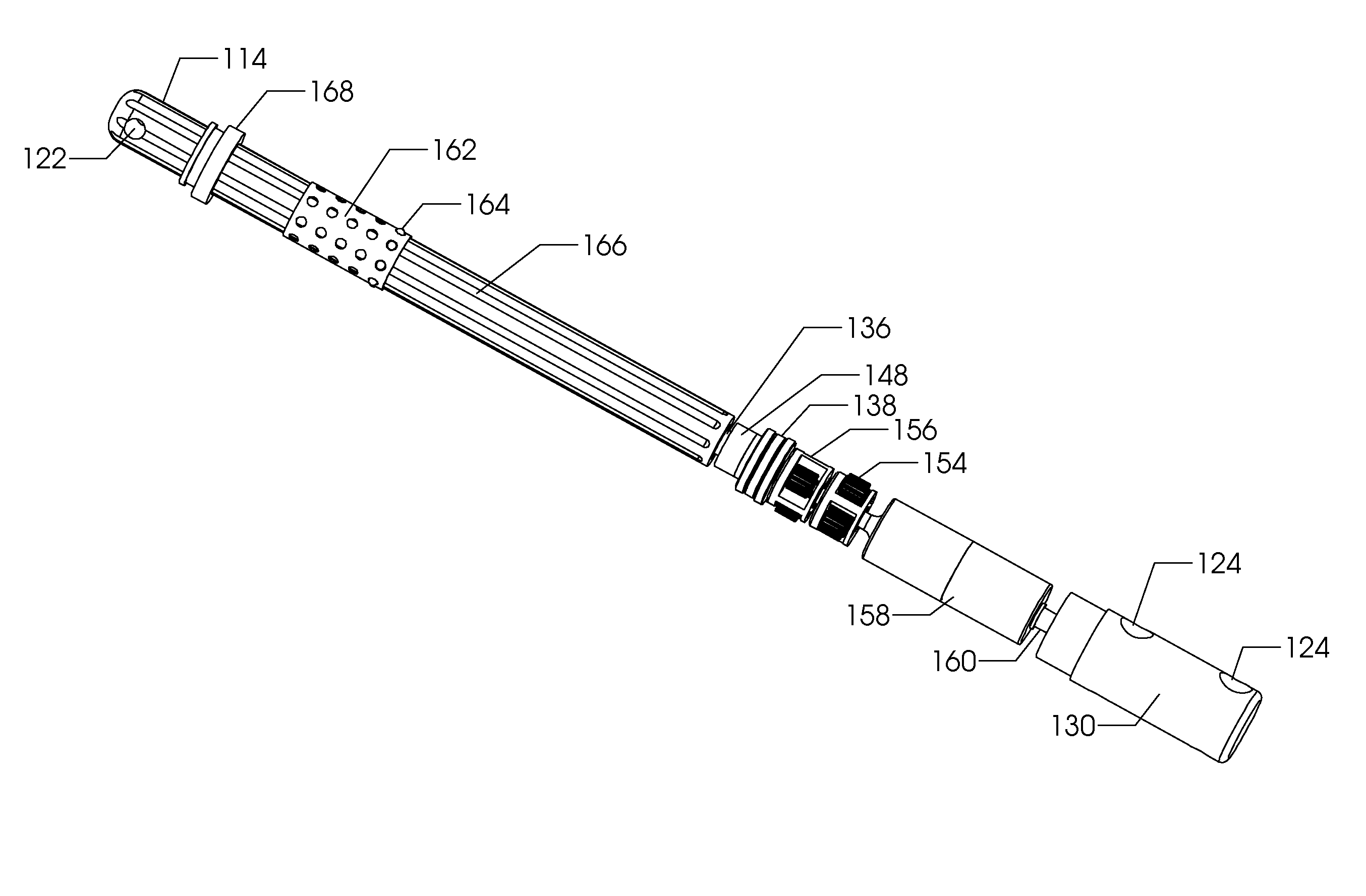
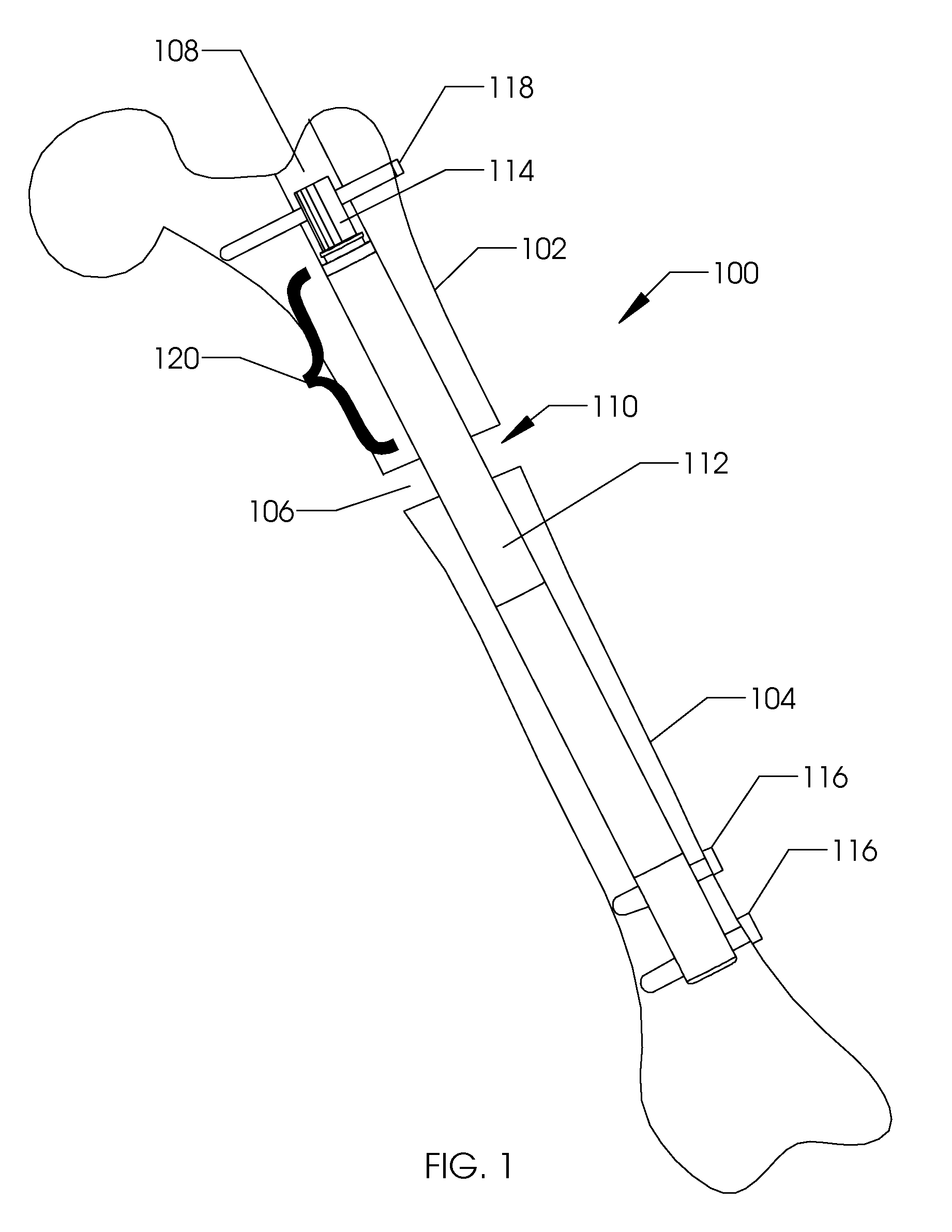
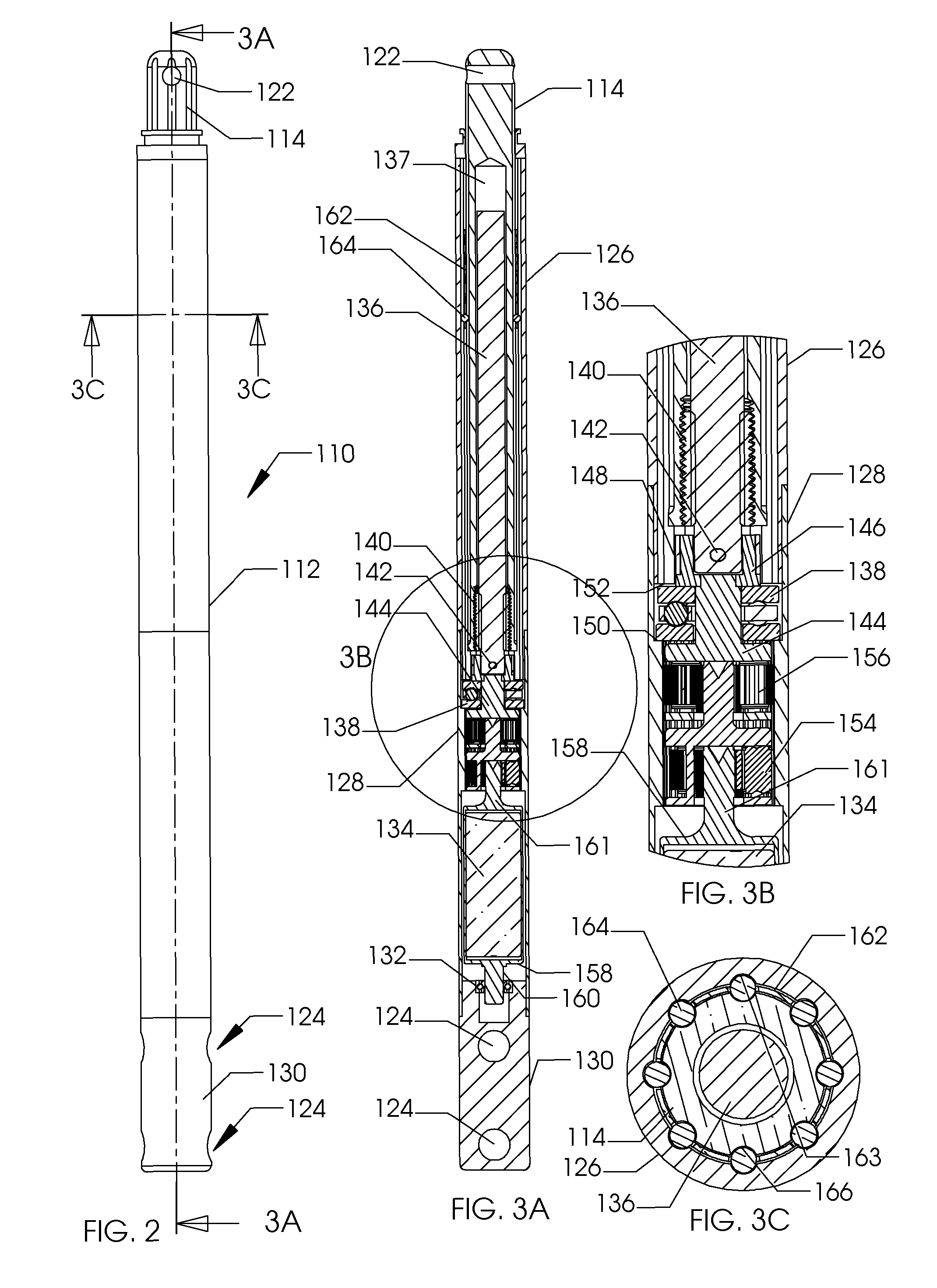
[0036]FIG. 1 illustrates the side view of an intramedullary lengthening device 110 which has been placed through a hole or bore 108 contained within a bone 100. The hole or bore 108 may be made by drilling, reaming and the like and may extend through both cortical bone (at the end) and through cancellous (spongy) bone. The intramedullary lengthening device 110 illustrated in FIG. 1 includes a housing 112 and a distraction shaft 114. In order to grow or lengthen the bone 100, the bone 100 either has a pre-existing separation 106 or is purposely cut or broken to create this separation 106, dividing the bone into a first section 102 and a second section 104. The cut may be done prior to inserting and securing the intramedullary lengthening device 110, or may be done after the device 110 is inserted, for example by use of a flexible Gigli saw. The distraction shaft 114 of the intramedullary lengthening device 110 is attached to the first section 102 using one or more attachment screws 1...


PUM


Abstract

An intramedullary lengthening device includes a housing and a distraction shaft. The intramedullary lengthening device is placed within a cavity of two bone sections (either already separated or purposely separated for insertion of the device). The distraction shaft of the intramedullary lengthening device is attached to the one of the bone sections using, for example, one or more attachment screws. The housing of the intramedullary lengthening device is attached to the second bone section using, for instance, one or more attachment screws. Over the treatment period, the bone is continually distracted, creating a new separation into which osteogenesis can occur. In one embodiment, the intramedullary lengthening device includes an actuator and an extension rod, which can be attached to one other.

Description

RELATED APPLICATIONS[0001]This Application claims priority to U.S. Provisional Patent Application No. 61 / 240,071 filed on Sep. 4, 2009 and U.S. Provisional Patent Application No. 61 / 363,986 filed on Jul. 13, 2010. The '071 and '986 Provisional Patent Applications are incorporated by reference as if set forth fully herein.FIELD OF THE INVENTION[0002]The field of the invention generally relates to medical devices for treating conditions involving the skeletal system and in particular bone growth applications.BACKGROUND OF THE INVENTION[0003]Distraction osteogenesis, also known as distraction callotasis and osteodistraction has been used successfully to lengthen long bones of the body. Typically, the bone, if not already fractured, is purposely fractured by means of a corticotomy, and the two segments of bone are gradually distracted apart, which allows new bone to form in the gap. If the distraction rate is too high, there is a risk of nonunion, if the rate is too low, there is a risk...

Claims


Application Information

Patent Timeline
Patent Type & Authority Patents(United States)
IPC IPC(8): A61B17/58
CPCA61B17/1725A61B17/7216A61B17/8875A61B17/8888A61B2017/681A61B17/58A61B17/7258A61B17/8866A61L2430/02A61B17/66
Inventor POOL, SCOTTWALKER, BLAIR
Owner NUVASIVE SPECIALIZED ORTHOPEDICS INC
Why Eureka
Try Eureka